Notebook computer heat radiation system based on tablet loop heat tube

A notebook computer, tablet loop technology, applied in the direction of electrical digital data processing, instruments, digital data processing components, etc., can solve the problem of inability to realize opening-closing repetition, flexible heat transfer, attenuation of heat transfer capacity of heat pipes, and space occupation and other problems, to avoid computer reliability problems, reduce volume and weight, and reduce battery power consumption

Inactive Publication Date: 2017-09-08
BEIJING INST OF SPACECRAFT SYST ENG
View PDF4 Cites 6 Cited by
  • Summary
  • Abstract
  • Description
  • Claims
  • Application Information

AI Technical Summary

Problems solved by technology

[0009] (1) The transmission path is still limited by the length. If the transmission path is too long, the heat transfer capacity of the heat pipe will decay as the length increases
In addition, the heat pipe must have a certain bending radius, which will take up space
The limitation of heat pipe bending and length still has certain restrictions on the layout design in the notebook
[0010] (2) The limitations of the traditional heat pipe structure make it impossible to use high-efficiency radiators. The heat pipes are cylindrical or flat, and it is difficult to design high-efficiency radiator samples
[0011] (3) It is impossible to realize the repeated and flexible heat transfer of opening-closing
Since traditional heat pipes cannot achieve flexible heat transfer, the heat from the chip cannot be transferred to the back of the screen
[0012] (4) Limited transmission capacity
With the continuous increase of chip power, the size, maximum heat transfer capacity and limit heat flux density of traditional heat pipes will not be able to meet the heat dissipation requirements of chips

Method used


Image

  • Notebook computer heat radiation system based on tablet loop heat tube
  • Notebook computer heat radiation system based on tablet loop heat tube
  • Notebook computer heat radiation system based on tablet loop heat tube

Examples


Embodiment Construction

[0035] The present invention will be described in detail below with reference to the accompanying drawings and examples.

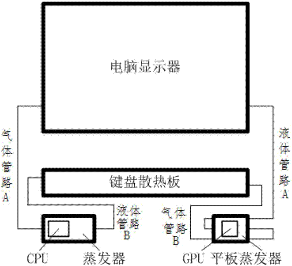
[0036] This embodiment provides a notebook computer heat dissipation system based on a flat loop heat pipe, which eliminates the fan and radiator components, can effectively reduce the installation space, facilitates internal layout design, improves operational reliability, and can eliminate the noise caused by the fan at the same time. Reduce power consumption requirements, increase computer standby and use time.

[0037] The system uses flat-plate loop heat pipes to collect, transfer, and dissipate heat from the CPU and graphics chips inside the laptop. Such as figure 1 As shown, the notebook computer cooling system based on the flat loop heat pipe includes: flat loop heat pipe evaporator, gas pipeline, liquid pipeline, screen back panel radiator, keyboard bottom panel radiator and flat panel evaporator. Among them, the flat-plate loop heat pipe evapor...


PUM


Abstract

The invention discloses a notebook computer heat radiation system based on tablet loop heat tubes. The notebook computer heat radiation system comprises a tablet loop heat tube evaporator, a screen back plate heat radiator, a keyboard bottom plate heat radiator and a tablet evaporator, wherein the tablet loop heat tube evaporator is clung to a computer CPU (Central Processing Unit) chip; steam flows through the screen back plate heat radiator through a pipeline, and then heat is diffused and condensed into a liquid through natural air convection; the liquid flows to the tablet evaporator which is clung to a display card GPU (Graphics Processing Unit) chip and is evaporated into steam; the steam flows to the keyboard bottom plate heat radiator through another pipeline and is cooled into a liquid through natural air convection, and then the liquid flows back to a liquid reservoir of the tablet loop heat tube evaporator. By adopting the heat radiation system, internal layout of a notebook computer is facilitated, a mounting space is effectively reduced, noise caused by a fan can be eliminated as fans and heat radiator components are not used, electric power consumption is reduced, and the standby and lasting time of a computer is prolonged.

Description

technical field [0001] The invention relates to a heat dissipation system, in particular to a notebook computer heat dissipation system, and belongs to the technical field of heat dissipation of electronic equipment. Background technique [0002] The loop heat pipe is a high-efficiency two-phase heat transfer device, which has the characteristics of high heat transfer performance, long-distance heat transfer, excellent temperature control characteristics, arbitrary bending of the pipeline, and convenient installation. With comparable advantages, the loop heat pipe has very broad application prospects in many fields such as aviation, aerospace, and ground electronic equipment heat dissipation. [0003] The loop heat pipe mainly includes an evaporator, a condenser, a liquid receiver, a vapor line and a liquid line. The whole cycle process is as follows: the liquid evaporates on the outer surface of the capillary core in the evaporator, absorbs the heat outside the evaporator,...

Claims


Application Information

Patent Timeline
Patent Type & Authority Applications(China)
IPC IPC(8): G06F1/20
CPCG06F1/203Y02D10/00
Inventor 满广龙张红星李国广励精图治
Owner BEIJING INST OF SPACECRAFT SYST ENG
Why Eureka
Try Eureka