Eureka AIR delivers breakthrough ideas for toughest innovation challenges, trusted by R&D personnel around the world.

Cutting fluid recovery treatment system and cutting fluid recovery treatment method

A treatment system and recycling technology, applied in water/sewage treatment, chemical instruments and methods, multi-stage water/sewage treatment, etc., can solve problems such as failure to pass national discharge standards

Inactive Publication Date: 2017-09-15
冯合生 +1
View PDF7 Cites 5 Cited by
  • Summary
  • Abstract
  • Description
  • Claims
  • Application Information

AI Technical Summary

Problems solved by technology

[0012] Because MVR evaporates and concentrates inorganic substances quite effectively (crystallization after concentration), but the organic hydrophilic group-based substances still cannot be effectively and completely resolved; organic water-soluble COD (chemical oxygen demand, environmental wastewater pollution index) (or It can be said that it is BOD (biochemical oxygen demand, pollution index of environmental waste water pollution)), when it partially contacts the surface of the body of the steam compressor, it will be converted from COD to VOC (volatile organic compound, environmental waste gas pollution index), and dissolved In water vapor, it causes gas-liquid equilibrium phenomenon, and it is discharged with the discharge of distilled water
As far as the cutting fluid treatment is concerned, the COD emission concentration is still about 5,000-10,000PPM (about 95% removal rate), which still cannot pass the national emission standard

Method used


Image

  • Cutting fluid recovery treatment system and cutting fluid recovery treatment method
  • Cutting fluid recovery treatment system and cutting fluid recovery treatment method
  • Cutting fluid recovery treatment system and cutting fluid recovery treatment method

Examples


Embodiment Construction

[0048] The preferred embodiments of the present invention will be described in detail below in conjunction with the accompanying drawings, so that the advantages and features of the present invention can be more easily understood by those skilled in the art, so as to define the protection scope of the present invention more clearly.

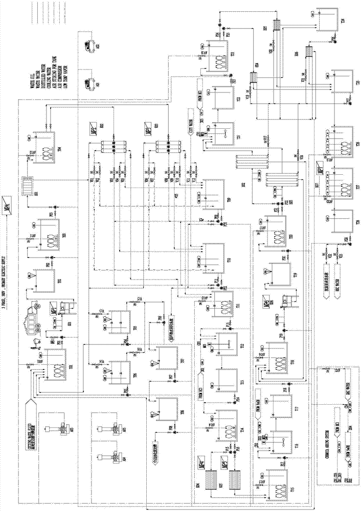
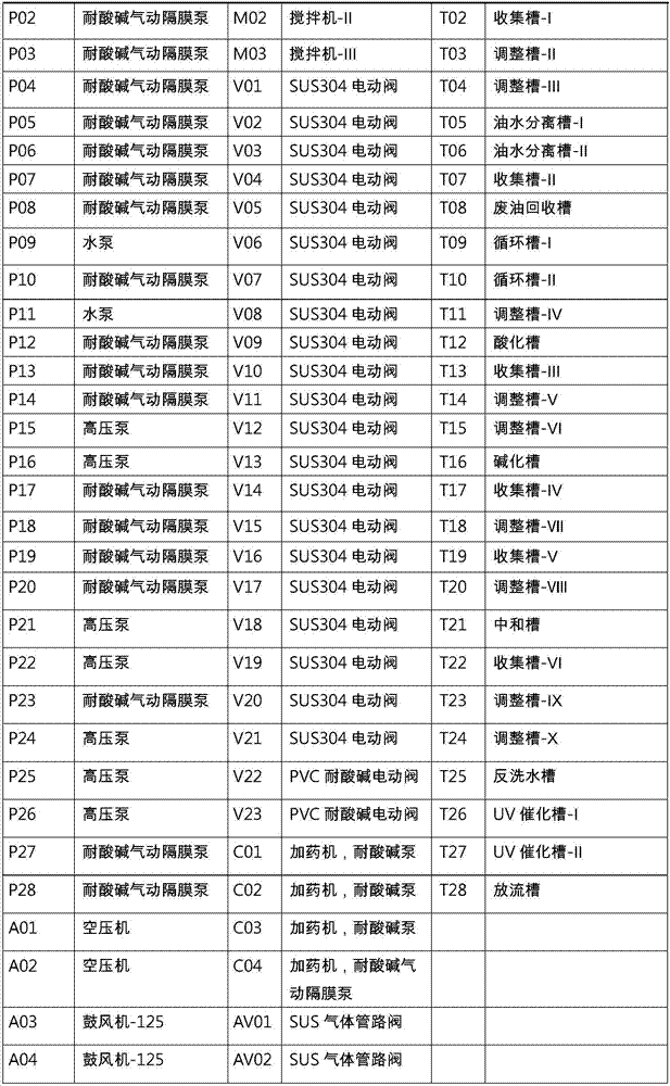
[0049] See attached figure 1 As shown, the cutting fluid recovery processing system and processing method in this embodiment include

[0050] 1. The first stage - dandruff and oil removal

[0051] 1. Actions before the system starts

[0052] Fill the circulation tank-IT09 and circulation tank-IIT10 with tap water to the highest water level; then repeatedly fill the discharge tank T28 with water to the medicine barrel D04; so that the medicine in D02 and D04 is completed.

[0053] 2. Soak medicine

[0054] Manually open the pipeline valve V23, close the valve V22, and the pump P28 is in the "ON" state to recycle the water (REC WATER) in the dis...


PUM


Abstract

The present invention discloses a cutting fluid recovery treatment system, which comprises a four-stage treatment system, wherein the four-stage treatment system comprises a first-stage treatment system, a second-stage treatment system, a third-stage treatment system and a fourth-stage treatment system, and the first-stage treatment system, the second-stage treatment system, the third-stage treatment system and the fourth-stage treatment system are sequentially connected through pumps. The cutting fluid recovery treatment method comprises: chip removing and degreasing; MVR demulsification and heat recovery; electro-coagulation oxidation and oil-water separation of concentrated water; and microtubule filtration, reverse osmosis filtration and UV oxidation. With the system and the method of the present invention, the COD in the cutting waste fluid is reduced to less than 100 PPM from the high concentration (the average concentration is 150000 PPM).

Description

technical field [0001] The invention relates to the technical field of industrial waste liquid treatment, in particular to a cutting fluid recovery treatment system and treatment method. Background technique [0002] 1. History [0003] Simple lathe industry, CNC lathe industry, milling machine industry, mechanical finishing industry and tool processing industry, etc., due to the relatively large production and service standards in the industry, some industries use lathes due to the fast speed of the mechanical shaft when processing metal appearance. The lathe drill bit and the surface of the material to be processed generate high heat due to friction. The industry often injects cutting fluid into the surface of the lathe drill bit and the processed material to cool, lubricate, clean and prevent rust, so that the cutting fluid and chips become the main pollutants. Since cooling is the main purpose of cutting, water accounts for about 90-95% in the composition of cutting flu...

Claims


Application Information

Patent Timeline
IPC IPC(8): C02F9/10
CPCC02F1/041C02F1/32C02F1/40C02F1/441C02F1/444C02F1/463C02F9/00
Inventor 冯合生冯韦纶
Owner 冯合生
Why Eureka
Eureka Blog
Learn More