
Strip material electroplating device

A technology of electroplating device and conductive wheel, which is applied to current conduction device, contact device, electrolysis process, etc., can solve the problems of reducing the performance of relays, hindered transmission, and too small gap, so as to save production costs, maintenance costs, and operation. Or maintenance time, the effect of reducing the wear and tear of spare parts

Pending Publication Date: 2017-09-15
厦门金越电器有限公司
View PDF7 Cites 3 Cited by
  • Summary
  • Abstract
  • Description
  • Claims
  • Application Information

AI Technical Summary

Problems solved by technology

Due to the sliding friction between metals, it is easy to scratch the copper strip; the sparks generated by the sliding will also burn the copper strip, and then cause peeling; the gap between the insulating rod and the copper strip that acts as a guide is fixed, and its Excessive clearance makes the copper strip 20' easy to swing and cause uneven coating
These have seriously affected the quality pass rate of the copper strip, which also reduces the performance of the relay, and the gap is too small to cause the transmission to be blocked.

Method used


Image

  • Strip material electroplating device
  • Strip material electroplating device
  • Strip material electroplating device

Examples


Embodiment Construction

[0028] To further illustrate the various embodiments, the present invention is provided with accompanying drawings. These drawings are a part of the disclosure of the present invention, which are mainly used to illustrate the embodiments, and can be combined with related descriptions in the specification to explain the operating principles of the embodiments. With reference to these contents, those skilled in the art should understand other possible implementations and advantages of the present invention. Components in the figures are not drawn to scale, and similar component symbols are generally used to denote similar components.

[0029] The present invention will be further described in conjunction with the accompanying drawings and specific embodiments.

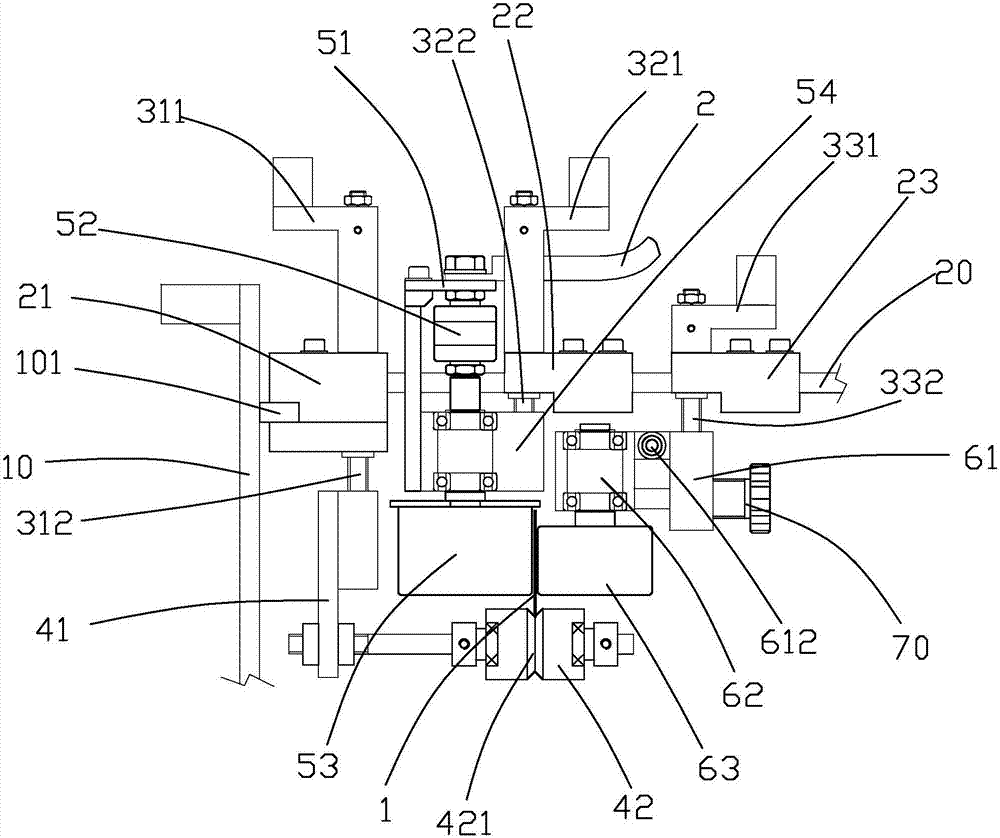
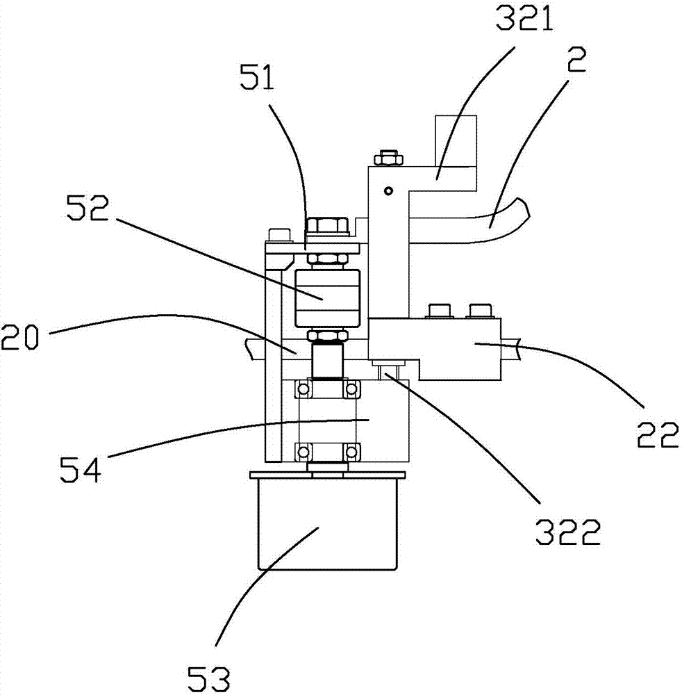
[0030] refer to Figure 2 to Figure 5 As shown, a strip electroplating device provided by the present invention includes: a support frame, a conductive wheel mechanism, a pressure wheel mechanism, a support wheel mecha...


PUM


Abstract

The invention provides a strip material electroplating device. The strip material electroplating device comprises a supporting frame, a conductive wheel mechanism, a pressing wheel mechanism and a supporting wheel mechanism, wherein the conductive wheel mechanism, the pressing wheel mechanism and the supporting wheel mechanism are arranged on the supporting frame. A pressing wheel of the pressing wheel mechanism cooperates with a conductive wheel of the conductive wheel mechanism to form a rolling clamping portion. A strip material is clamped by the rolling clamping portion and is in electric contact with the conductive wheel. The rolling and clamping portion has the functions of clamping and guiding and also achieves rolling electric conduction with the strip material. A supporting wheel of the supporting wheel mechanism is located at the bottom of the strip material. The supporting wheel has the function of supporting, achieves rolling guiding of the bottom of the strip material and avoids the bottom of the strip material from conducting electricity. The strip material is not prone to being scratched, and sparks caused by friction are avoided. In this way, the quality problems, such as scratches, scorching, peeling and an uneven plating layer, caused by sliding electric conduction are fundamentally solved.

Description

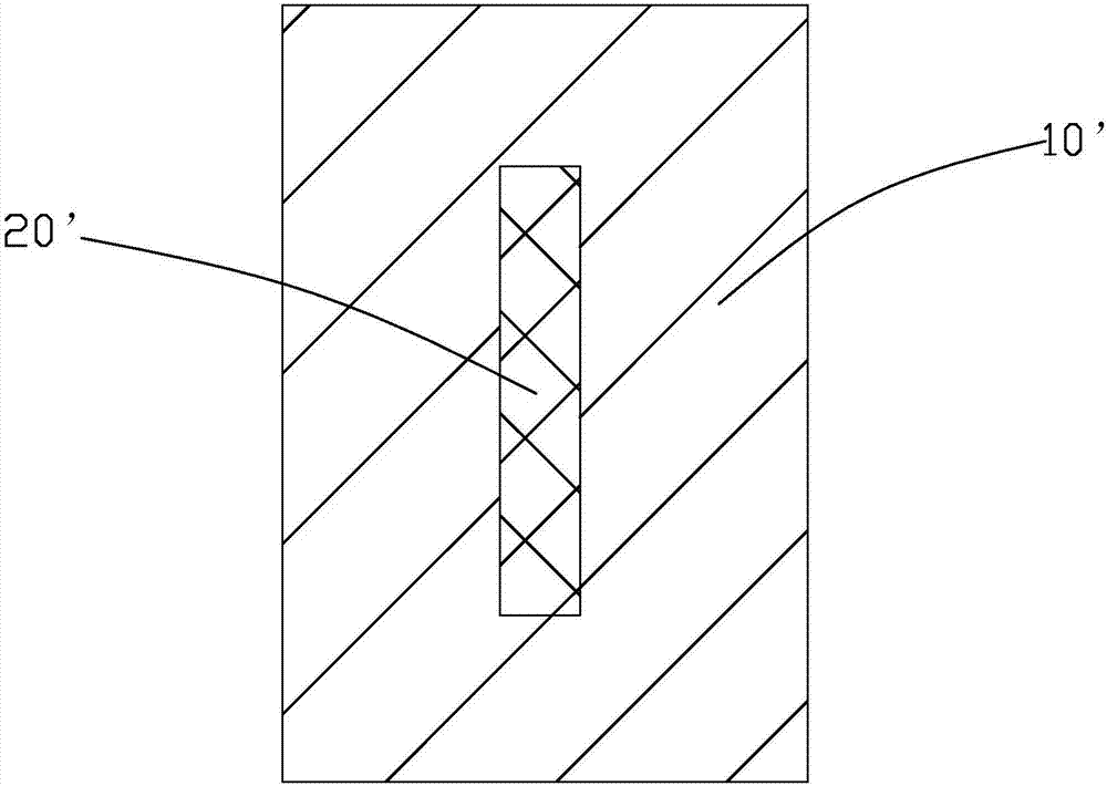
technical field [0001] The invention relates to the technical field of electroplating equipment manufacturing, in particular to an electroplating device for continuous electroplating with strip materials. Background technique [0002] Continuous electroplating can improve the wear resistance, electrical conductivity, and reflective properties of the workpiece, thereby improving the practicability and decoration of the workpiece, so it is widely used, second only to rack plating and barrel plating, and its types can be divided into Partial plating, spot plating, rainbow plating, pearl plating, etc. [0003] In the prior art, the electroplating method for strip material (such as copper strip) is as follows: figure 1 As shown, the conduction mode of the current plating tank is very simple, and the copper strip 20' is guided by the insulating rods (not shown) on both sides, and the current is obtained by direct friction with the stainless steel rod 10' connected to the power su...

Claims


Application Information

Patent Timeline
IPC IPC(8): C25D7/06C25D17/00
CPCC25D7/0657C25D17/005C25D17/007
Inventor 李国华方国富
Owner 厦门金越电器有限公司
Learn More