Linear piezoelectric motor

A piezoelectric motor and linear technology, applied in electrical components, piezoelectric effect/electrostrictive or magnetostrictive motors, generators/motors, etc., can solve the problem of low output speed, fast wear, complex structure and control circuits and other problems, to achieve the effect of less energy loss, high output speed and simple structure

Active Publication Date: 2017-09-15
HEFEI UNIV OF TECH
View PDF6 Cites 7 Cited by
  • Summary
  • Abstract
  • Description
  • Claims
  • Application Information

AI Technical Summary

Problems solved by technology

Quasi-static motors mainly include inertial impact motors, inchworm motors, etc. Inertial impact motors have a simple structure, are easy to control, have a large driving force, and have high resolution, but they use asymmetrical waveforms to excite motion, and the friction surface works rough, with sliding friction , fast wear, correspondingly low efficiency and short life
The inchworm motor guides the mover to move in one direction through the cooperation of three sets of piezoelectric elements. It has no sliding friction, high efficiency, and large output force (up to thousands of N). However, its structure and control circuit are relatively complicated, and the operating frequency is low. Its output speed is low

Method used


Image

  • Linear piezoelectric motor
  • Linear piezoelectric motor
  • Linear piezoelectric motor

Examples


Embodiment

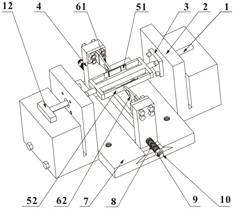
[0049] see figure 1 , a linear piezoelectric motor includes a drive preload mechanism, an output mechanism and a bearing seat 2.

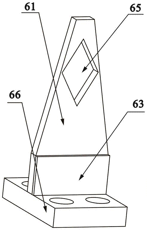
[0050] The driving pretension mechanism includes a pair of driving oscillators. A pair of drive vibrator is symmetrically installed on the base 7 through a pair of upright dovetail seats 4, and the position can be adjusted on the base 7. Positioning rod 10 runs through and is connected with a pair of dovetail seat 4; Tightening nut 9, spring 8 is sleeved on the screw rod between dovetail seat 4 and pre-tightening nut 9. A pair of driving vibrator consists of a first driving vibrator 61 and a second driving vibrator 62, see image 3 , the first driving vibrator 61 is provided with a third piezoelectric sheet 63, and the second driving vibrator 62 is provided with a fourth piezoelectric sheet 64;

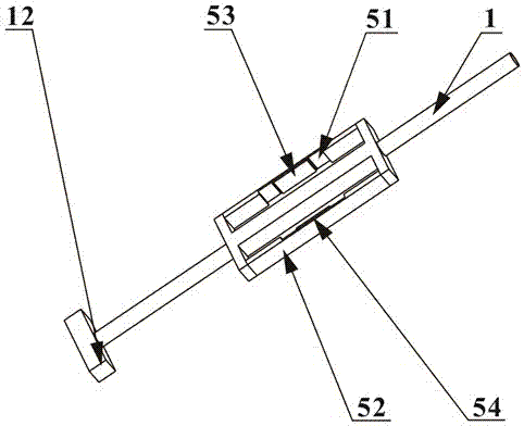
[0051] see figure 2 , the output mechanism includes an output rod 1, the two ends of the output rod 1 are optical axes, one end of which is connecte...


PUM


Abstract

The invention relates to a linear piezoelectric motor. The linear piezoelectric motor includes a drive pre-tensioning mechanism, an output mechanism and a bearing pedestal, wherein the drive pre-tensioning mechanism includes a pair of driving vibrators on the pedestal; the pair of driving vibrators are each provided with a vibrator piezoelectric patch; the output mechanism includes an output rod; the middle part of the output rod is provided with a +-shaped framework in the axial direction; two side bars of the +- shaped framework are vibration plates; and the vibration piezoelectric patches are arranged on the vibration plates. The linear piezoelectric motor controls the bending vibration modal of the vibration plates and the driving vibrators by means of the waveform synthesis principle so as to form coordinate action between the vibration plates and the driving vibrators to realize linear motion, and does not generate sliding friction in theory, thus being less in energy loss and being high in efficiency. The operating frequency of the linear piezoelectric motor is greater than 2000Hz; the linear piezoelectric motor has high output speed and has two operating states; and the linear piezoelectric motor can realize low speed high torque output and high speed low torque output through high and low level coordination of the first and second driving vibrators.

Description

technical field [0001] The invention belongs to the technical field of precision driving and positioning, and in particular relates to a linear piezoelectric motor. Background technique [0002] Piezoelectric motors use the inverse piezoelectric effect of piezoelectric ceramics to convert electrical energy into mechanical energy. Due to its small size, large torque, high precision, good low-speed performance, and no electromagnetic interference, it has broad application prospects in the fields of aerospace, missiles, robots, and precision instruments. The linear piezoelectric motor has the characteristics of direct output of linear motion and self-locking when power is off. It has been used in precision positioning systems, biological injection equipment, mobile phone cameras, and automotive electric remote control mirrors. [0003] At present, linear piezoelectric motors are mainly divided into traveling wave motors, standing wave motors, and quasi-static motors. The trav...

Claims


Application Information

Patent Timeline
Patent Type & Authority Applications(China)
IPC IPC(8): H02N2/00
CPCH02N2/0015H02N2/005
Inventor 贺良国楚宇恒王勇谷先广赵小勇李新宇庞席德余建
Owner HEFEI UNIV OF TECH
Why Eureka
Try Eureka