Sensorless initial position detecting method for permanent magnet synchronous motor

A permanent magnet synchronous motor, initial position detection technology, applied in the direction of control of electromechanical transmission, control of generator, motor control, etc., can solve the problems of zero-crossing point solution, too long time for magnetic pole judgment stage, etc.

Active Publication Date: 2017-09-15
BEIHANG UNIV
View PDF3 Cites 13 Cited by
  • Summary
  • Abstract
  • Description
  • Claims
  • Application Information

AI Technical Summary

Problems solved by technology

[0005] The technical problem to be solved by the present invention is: the purpose of the present invention is to overcome the deficiencies of the prior art, solve the problem of solving the zero-crossing point caused by the traditional pulse vibration high-frequency injection method, and correct the problem of too long time in the magnetic pole judgment stage

Method used


Image

  • Sensorless initial position detecting method for permanent magnet synchronous motor
  • Sensorless initial position detecting method for permanent magnet synchronous motor
  • Sensorless initial position detecting method for permanent magnet synchronous motor

Examples


specific Embodiment approach 1

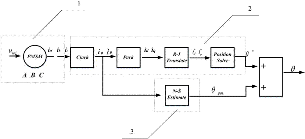
[0055] Specific implementation mode one: see figure 1 Describe this embodiment, a sensorless initial position detection method of a permanent magnet synchronous motor described in this method is a position detection method based on a virtual pulse vibration high-frequency injection method, which is characterized in that it includes a permanent magnet synchronous motor mathematical model part 1 , Position solution part 2 and magnetic pole correction part 3.

[0056] The mathematical model part 1 of the permanent magnet synchronous motor includes system voltage equations and flux linkage equations. The position calculation part 2 is a preliminary judgment of the rotor position based on the virtual pulse vibration high-frequency injection method. When the motor is at rest, assume that the rotor has a high rotational speed ω * r , to establish the corresponding virtual synchronous rotating coordinate system d * -q * , and the initial state d of the virtual coordinate system ...

specific Embodiment approach 2

[0057] Specific embodiment 2: This embodiment is a further limitation of the permanent magnet synchronous motor rotor position detection device based on the virtual pulse vibration high-frequency injection method described in the specific embodiment 1. The mathematical model part of the permanent magnet synchronous motor 1 , including the system voltage equation and the flux linkage equation, as shown in formula (1) and formula (2) respectively.

[0058] The voltage equation in the natural coordinate system:

[0059]

[0060] The flux linkage equation is:

[0061]

[0062] Among them, ψ 3s is the flux linkage of the three-phase winding; u 3s ,R,i 3s Respectively, the phase voltage, resistance and current of the three-phase winding; L 3s is the inductance of the three-phase winding, F 3s is a sinusoidal function matrix with a phase difference of 120°, and satisfies:

[0063] i A , i B , i C is the three-phase current, R is the phase resistance, u A , u B , ...

specific Embodiment approach 3

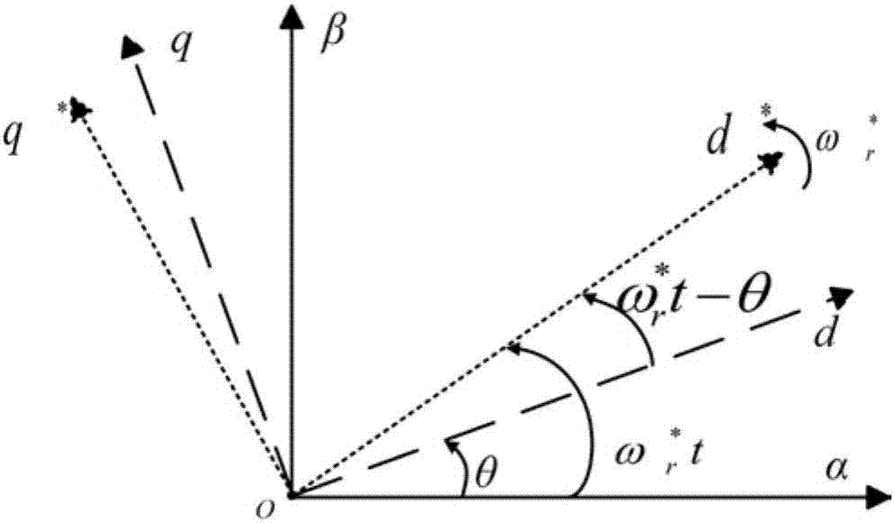
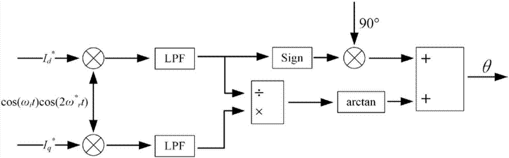
[0064] Specific implementation mode three: see figure 2 , 3 This embodiment is described. This embodiment is a further limitation of the permanent magnet synchronous motor rotor position detection device based on the virtual pulse vibration high-frequency injection method described in the first embodiment. The position calculation part 2 includes the following steps:

[0065] Step 1: Inject a high-frequency voltage signal into the virtual direct axis and solve the current response in the virtual synchronous rotating coordinate system. according to figure 2 The coordinate relationship transformation shown includes:

[0066] Clark transformation:

[0067]

[0068] PARK transformation:

[0069]

[0070] Transformation between virtual-real synchronously rotating coordinate systems:

[0071]

[0072] Among them, ω * r is the assumed motor speed;

[0073] Inject a high-frequency voltage signal U into the virtual direct axis i cos ω i t, transform it into the act...


PUM


Abstract

The invention relates to a sensorless initial position detecting method for a permanent magnet synchronous motor. The sensorless initial position detecting method comprises the steps of: adopting a virtual pulsating high-frequency injection method for calculating a rotor position, injecting a high-frequency voltage into a virtual direct axis, establishing a virtual rotating coordinate system, utilizing the virtual rotating coordinate system and a mathematical model of a permanent magnet synchronous motor coordinate system to calculate straight-axis and quadrature-axis currents, multiplying a straight-axis current signal and a quadrature-axis current signal by a voltage frequency containing an injection signal and a cosine value of an assumed rotational frequency simultaneously and separately, subjecting the results to low-pass filtering, and deriving out arc tangent of the two currents after filtering to obtain the rotor position preliminarily; and utilizing a sine and cosine relationship between the straight-axis and quadrature-axis currents to further obtain the rotor position, adopting a carrier frequency component method to replace a secondary injection method for conducting magnetic pole judgment, and correcting N-S poles to obtain the actual rotor position. The sensorless initial position detecting method has the advantages of high precision and simple implementation, and can be used for improving the sensorless starting control precision of the permanent magnet synchronous motor used for fans, pumps, compressors or electric vehicles.

Description

technical field [0001] The invention belongs to the technical field of motor control, and in particular relates to a sensorless initial position detection method of a permanent magnet synchronous motor. Background technique [0002] The permanent magnet synchronous motor uses permanent magnets to provide excitation. Compared with the electric excitation motor, the loss of the excitation system is reduced, and the efficiency and power density of the motor are greatly improved. At the same time, it overcomes the unfavorable factors brought by DC motor brushes and commutators, and its application scope has rapidly developed from the initial military industry to aerospace, industrial automation and other fields. [0003] Due to the requirements of the drive system, permanent magnet synchronous motors usually add mechanical sensors such as Hall sensors and photoelectric encoders to obtain rotor position information. The advantages are high precision and precise control. But it w...

Claims


Application Information

Patent Timeline
Patent Type & Authority Applications(China)
IPC IPC(8): H02P21/00H02P21/18H02P21/32H02P25/026
CPCH02P21/0017H02P21/18H02P21/32H02P25/03H02P2203/11
Inventor 刘刚洪琨宋欣达郑世强韩邦成
Owner BEIHANG UNIV
Why Eureka
Try Eureka