New winding method of emi common mode inductor and its winding method

A common mode inductance and winding technology, applied in the production field of toroidal common mode inductance coils, can solve the problems of many technical requirements of staff, inability to realize automatic winding, and inability to machine butterfly winding, etc., and meet the requirements of staff Low cost, manpower saving, simple winding method

Active Publication Date: 2019-01-18
SHANDONG ZHONGRUI ELECTRONICS
View PDF8 Cites 0 Cited by
  • Summary
  • Abstract
  • Description
  • Claims
  • Application Information

AI Technical Summary

Problems solved by technology

[0008] Although the general butterfly winding method can meet the electromagnetic interference requirements of the toroidal common mode inductor, the multi-layer butterfly winding method requires a beautiful butterfly shape, which is prone to adverse phenomena such as winding deviation, small closing, chaotic winding, and collapsed wires. Automatic winding is realized, and there are many technical requirements for the staff, otherwise the EMI effect cannot be guaranteed. Generally, new employees need 2-3 months to master the winding skills, which will cause a lot of waste of materials during the period, thereby increasing costs.
Restricted by the starting winding method and winding distribution method of the middle branch line, it is impossible to use the machine to realize the butterfly winding. With the increase of labor costs year by year, the cost pressure is getting bigger and bigger.

Method used


Image

  • New winding method of emi common mode inductor and its winding method
  • New winding method of emi common mode inductor and its winding method
  • New winding method of emi common mode inductor and its winding method

Examples


Embodiment Construction

[0028] In order to make the technical problems, technical solutions and advantages to be solved by the present invention clearer, the following will describe in detail with reference to the drawings and specific embodiments.

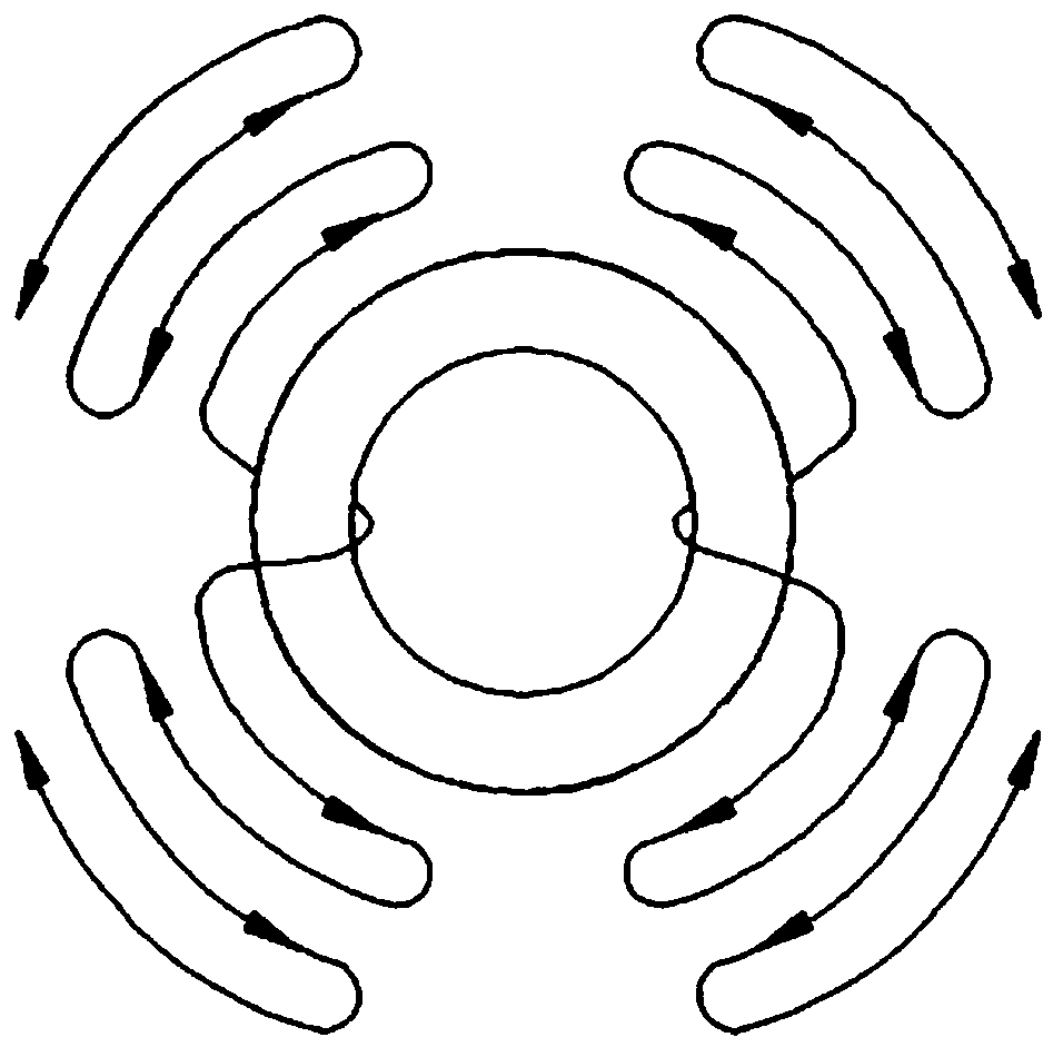
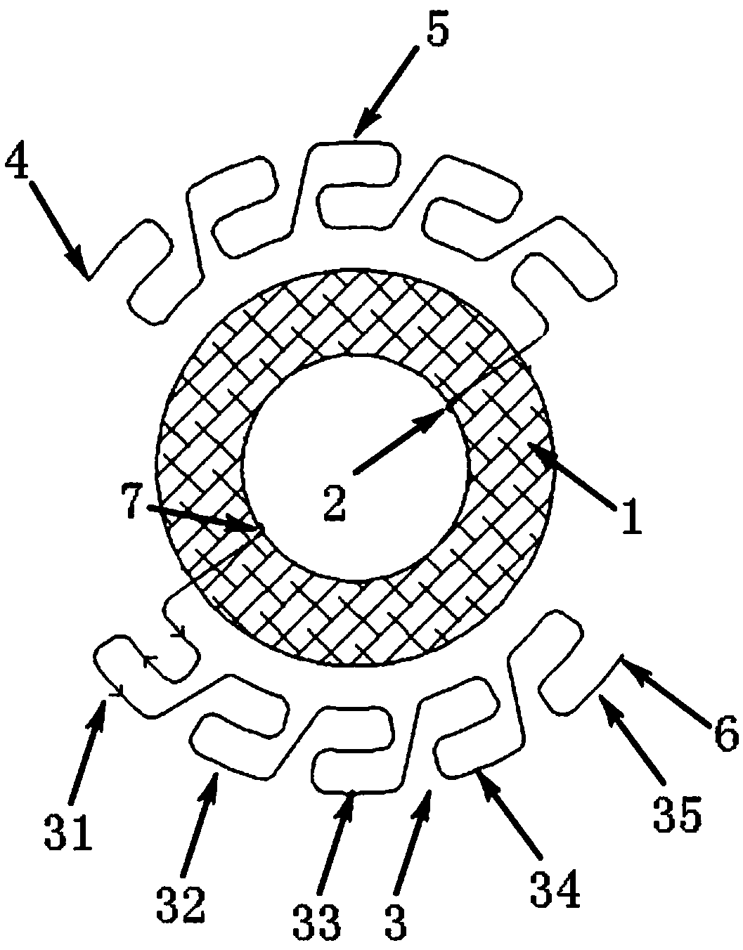
[0029] The present invention provides a kind of EMI common mode inductor of novel winding method, such as figure 2 As shown, it includes a ring core 1, two windings 3, 5 and four lead ends 2, 4, 6 and 7 wound symmetrically on both sides of the ring core 1, and each winding 3 or 5 is a multi-segment winding 31, 32, 33, 34 and 35, the number of winding layers of each winding is multi-layer; the two lead ends of each winding are respectively located at both ends of the winding, and one of the lead ends is located at the innermost layer 2 of the winding (or 7), the other lead end is located in the outermost layer 4 (or 6) of the winding.

[0030] The inventors have found that by fixing one end for winding, automatic winding can be realized, but the anti-el...


PUM


Abstract

The embodiments of the present invention disclose an EMI common-mode inductor of a new winding method and a winding method for the EMI common-mode inductor, relating to the technical field of common-mode inductors. The EMI common-mode inductor of the new winding method comprises a toroidal magnetic core, and wound at symmetric positions on two sides of the toroidal magnetic core, two windings and four lead ends. Each winding is a multi-segment winding, and multiple layers are wound around each segment of a winding. Two lead ends of each winding are disposed at two ends of the winding respectively, and one of the lead ends is positioned at the innermost layer of the winding and the other lead end is positioned at the outermost layer of the winding. The embodiments of the present invention can ensure EMI effect, realize automatic winding, effectively improve production efficiency, greatly save labor, lower reject ratio, reduce product cost, and achieve win-win between a client and a supplier.

Description

technical field [0001] The invention relates to the field of production operations of annular common-mode inductance coils in power electronic circuits, in particular to a novel winding method of EMI common-mode inductance and a winding method thereof. Background technique [0002] EMI common mode inductors are two sets of wires wound on the ferrite magnetic ring. There are generally three winding methods: C-shaped winding, Z-shaped winding, and butterfly winding. Among them, butterfly winding is the most used and has the best EMI effect. Shape winding generally accounts for more than 70% of the market. [0003] When the inductance components work at high frequency, the distributed capacitance will have a great impact on the working state of the inductance components, such as causing oscillation of the waveform, EMC deterioration, heating of the inductance components, etc., which will have a great impact on its performance influences. Among them, the parasitic parameters o...

Claims


Application Information

Patent Timeline
Patent Type & Authority Patents(China)
IPC IPC(8): H01F17/06H01F27/30H01F41/066H01F41/08
CPCH01F17/06H01F27/306H01F41/066H01F41/08H01F2017/0093H01F2017/065
Inventor 高启龙谢真葛萍萍尹付祥徐鸿彬杨树吴楠
Owner SHANDONG ZHONGRUI ELECTRONICS
Why Eureka
Try Eureka