A corrosion-resisting electric pole for electric power and applications thereof
A corrosion-resistant, electric pole technology, applied in the field of electric pole equipment, can solve the problems of poor corrosion resistance and low strength of electric poles, and achieve the effects of good corrosion resistance, high strength and reduced weight
- Summary
- Abstract
- Description
- Claims
- Application Information
AI Technical Summary
Problems solved by technology
Method used
Image
Examples
Embodiment 1
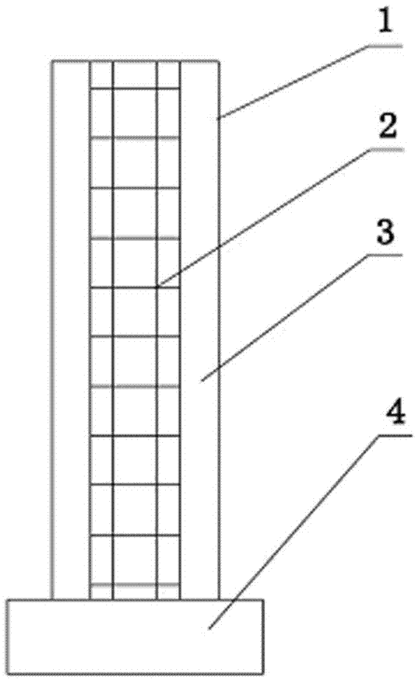
[0026] like figure 1 As shown, the corrosion-resistant electric pole, the pole 1 includes a steel frame 2 and a concrete layer 3 wrapping the steel frame, the lower end of the pole 1 is provided with a steel plate end 4, and the steel plate end 4 is connected by a steel wire fixed on pole 1.
[0027] The corrosion-resistant electric pole is prepared according to the following process:
[0028] Take each raw material according to the weight part for later use, wherein: 20 parts of quartz sand, 20 parts of fly ash, 10 parts of gravel, 10 parts of blast furnace slag, 5 parts of desulfurized gypsum, 3 parts of straw powder, 1 part of foaming agent, and 30 parts of water; The slurry obtained after mixing the above raw materials evenly has self-leveling properties. The slurry is poured into a mold pre-installed with a steel skeleton. After 24 hours, the mold is demoulded, and then the end of the steel plate is connected and fixed on the pole through a steel wire.
[0029] The part...
Embodiment 2
[0032] like figure 1 As shown, the corrosion-resistant electric pole, the pole 1 includes a steel frame 2 and a concrete layer 3 wrapping the steel frame, the lower end of the pole 1 is provided with a steel plate end 4, and the steel plate end 4 is connected by a steel wire fixed on pole 1.
[0033] The corrosion-resistant electric pole is prepared according to the following process:
[0034] Take each raw material according to the weight part for later use, including: 30 parts of quartz sand, 30 parts of fly ash, 15 parts of stone, 15 parts of blast furnace slag, 9 parts of desulfurized gypsum, 5 parts of straw powder, 2 parts of foaming agent, and 50 parts of water; The slurry obtained after mixing the above raw materials evenly has self-leveling properties. The slurry is poured into a mold pre-installed with a steel skeleton. After 24 hours, the mold is demoulded, and then the end of the steel plate is connected and fixed on the pole through a steel wire.
[0035] The pa...
Embodiment 3
[0038] Taking common cement concrete electric poles as a control group, the various performances of electric poles of the present invention have been detected, specifically in Table 1:
[0039] Table 1
[0040] performance
[0041] Conclusion: The power pole of the present invention has higher flexural and compressive strength than cement concrete poles commonly used in the market, can be used instead, and saves raw material costs.
PUM
| Property | Measurement | Unit |
|---|---|---|
| Particle size | aaaaa | aaaaa |
| Particle size | aaaaa | aaaaa |
| Particle size | aaaaa | aaaaa |
Abstract
Description
Claims
Application Information
 - R&D
- Intellectual Property
- Life Sciences
- Materials
- Tech Scout
- Unparalleled Data Quality
- Higher Quality Content
- 60% Fewer Hallucinations
Browse by: Latest US Patents, China's latest patents, Technical Efficacy Thesaurus, Application Domain, Technology Topic, Popular Technical Reports.
© 2025 PatSnap. All rights reserved.Legal|Privacy policy|Modern Slavery Act Transparency Statement|Sitemap|About US| Contact US: help@patsnap.com

