Ka-band high-power linearly-circularly polarized converter

A converter and high-power technology, applied in the field of Ka-band electromagnetic wave line-circular polarization converter, can solve the problems of complex structure of the polarization converter system, low cross-polarization level of transmission loss, large transmission loss, etc., and achieve Meet the requirements of high-power operation, the effect of low structural transmission loss and low cross-polarization level

Inactive Publication Date: 2017-09-29
UNIV OF ELECTRONICS SCI & TECH OF CHINA
View PDF4 Cites 9 Cited by
  • Summary
  • Abstract
  • Description
  • Claims
  • Application Information

AI Technical Summary

Problems solved by technology

[0006] Aiming at the deficiencies of the complex structure of the polarization converter system and large transmission loss in the background technology, the present invention proposes a transmissive Ka-band high-power line-circular polarization converter, which has the advantages of small transmission loss and low cross-polarization level , wide working bandwidth, simple structure, convenient processing, etc.

Method used


Image

  • Ka-band high-power linearly-circularly polarized converter
  • Ka-band high-power linearly-circularly polarized converter
  • Ka-band high-power linearly-circularly polarized converter

Examples


Embodiment example 1

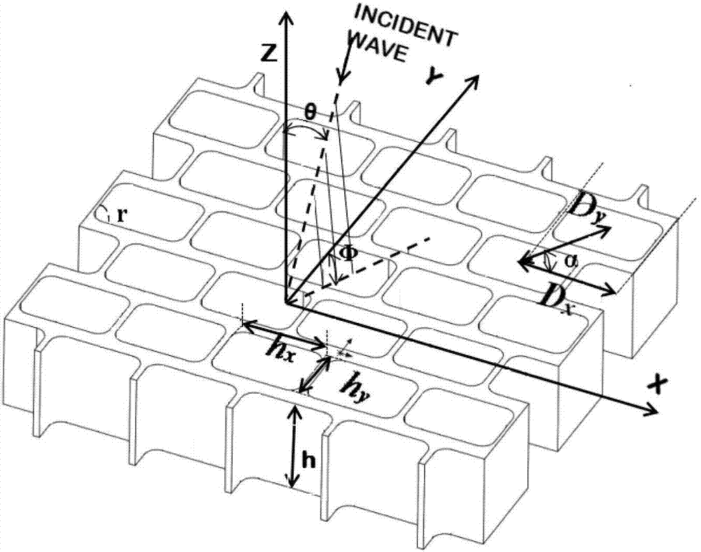
[0043] This embodiment takes a single-layer polarization converter with a working center frequency of 35 GHz as an example. The dimensions of each part are: h x =6.3mm, h y =5.45mm, D x =7.8mm, D y =11.9mm, r=1mm, h=15mm, incident angle θ=0°.

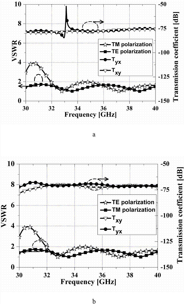
[0044] Such as image 3 Shown are the cross-polarization levels and standing wave ratios of the monolayer structure, where T yx Indicates the transmission coefficient of linearly polarized waves polarized on the X axis to the polarization on the Y axis, T xy Indicates the transmission coefficient of linearly polarized waves polarized on the Y axis to those polarized on the X axis. (a) In the figure Φ=-45°, the outgoing wave is a left-handed circularly polarized wave. The transmission coefficients of the two orthogonally polarized components are both less than -50dB, and the standing wave ratio is less than 2 in the passband range of 32GHz-40GHz; (b) Φ = 45 ° in the figure, and the outgoing wave is a right-handed circularly polari...

Embodiment example 2

[0048] This embodiment takes a double-layer polarization converter with a working center frequency of 35 GHz as an example. In this embodiment, the dimensions of each part are: h x = 6mm, h y =5.37mm, D x =7.3mm, D y =11.74mm, r=1mm, the thickness of a single metal plate h=8mm, the distance between two metal plates t=2mm, and the incident angle θ=0°.

[0049] Such as Figure 5 Shown is the cross-polarization level and standing wave ratio of the double-layer structure, (a) Φ=-45° in the figure, and the outgoing wave is a left-handed circularly polarized wave. The transmission coefficients of the two orthogonally polarized components are both less than -55dB, and the standing wave ratio is less than 2 in the passband range of 31.8GHz-37.7GHz; (b) Φ=45° in the figure, and the outgoing wave is right-handed circular polarization Wave. The transmission coefficients of the two orthogonally polarized components are both less than -60dB, and the standing wave ratio is less than 2...


PUM


Abstract

The invention discloses a Ka-band high-power linearly-circularly polarized converter, and belongs to the technical field of high-power millimeter waves. The converter comprises a supporting structure, a fixing circular ring, an installing stop ring and a metal circular plate. Polarization conversion is realized by the rectangular hole structures periodically arranged on the metal circular plate. The structure has the advantages of being simple in design principle, convenient to process, wide in work frequency band and low in cross polarization level. The rectangular holes are arranged in an isosceles triangle so that the relative space between the units is enabled to be reduced and the influence of grating lobes can be effectively reduced; and quarter arc segments are used as the four corners of the rectangular unit holes so that the local field intensity of the edges and the corners can be reduced, the power capacity of the device can be enhanced and the high-power work requirement can be met. The inclined angle of the metal circular plate and the polarization direction of the incident linearly polarized waves can be adjusted so that selection and switching of left-hand circular polarization and right-hand circular polarization of the emergent waves can be realized; meanwhile, the converter also has the advantages of low transmission loss and great heat radiation.

Description

technical field [0001] The invention belongs to the technical field of high-power millimeter waves, and in particular relates to a Ka-band electromagnetic wave line-circular polarization converter. Background technique [0002] Electromagnetic waves propagated in space are divided into linearly polarized waves, elliptical polarized waves, and circularly polarized waves according to the polarization method. Compared with other polarized waves, circularly polarized waves have a hand-directed orthogonality, which can suppress rain and fog interference and resist multipath effects. In aerospace communication and telemetry and remote sensing equipment, circularly polarized waves are used for transmission. In addition to reducing signal loss, it can also eliminate the influence of polarization distortion caused by the Faraday rotation effect of the ionosphere. Therefore, circularly polarized waves have a wide range of applications in communications, radar, telemetry and remote se...

Claims


Application Information

Patent Timeline
Patent Type & Authority Applications(China)
IPC IPC(8): H01Q15/24
CPCH01Q15/244
Inventor 吴泽威张婷王丽王建勋蒲友雷罗勇
Owner UNIV OF ELECTRONICS SCI & TECH OF CHINA
Why Eureka
Try Eureka