Method and master base station for positioning labels in wireless network

A technology of positioning tags and wireless networks, applied in the field of positioning tags, methods and main base stations, can solve the problems that base station identification cannot be stabilized, fail, waste operations, etc., and achieve the effect of reducing time, short path and long life.

Active Publication Date: 2017-10-03
BEIJING XINWANG RUIJIE NETWORK TECH CO LTD
2 Cites 22 Cited by

AI-Extracted Technical Summary

Problems solved by technology

[0014] It can be seen that in the prior art, the ranging operation will not start until the tag receives the base station ID. If the tag receives the timeout, the positioning will fail this time, and all previous operations will be wasted.
Therefore, whether the base station identification can be s...

Abstract

The embodiment of the invention provides a method for positioning labels in a wireless network. The method comprises the following steps that the master base station obtains identifiers of slave base stations, wherein the slave base stations and the master base station are located in the same target area, and the number of the slave base stations is greater than or equal to 2; the master base station receives broadcasting messages sent by the labels and sends the identifier of the master base station and the identifiers of the slave base stations to the labels when the labels are in the target area; and the master base station obtains a second distance measurement result and sends a first distance measurement result and the first distance measurement result to a server. The embodiment of the invention also provides the master base station for positioning the labels in the wireless network. Compared with an existing UWB (Ultra Wideband) positioning scheme, the labels are allocated and managed at base station ends, so paths as short as possible are employed, the instable delay and factors are reduced to the lowest, and the positioning system is relatively reliable.

Application Domain

Technology Topic

Wireless mesh networkDistance measurement +4

Image

  • Method and master base station for positioning labels in wireless network
  • Method and master base station for positioning labels in wireless network
  • Method and master base station for positioning labels in wireless network

Examples

  • Experimental program(1)

Example Embodiment

[0057] The technical solutions in the embodiments of the present invention will be clearly and completely described below in conjunction with the accompanying drawings in the embodiments of the present invention. Obviously, the described embodiments are only a part of the embodiments of the present invention, rather than all the embodiments. Based on the embodiments of the present invention, all other embodiments obtained by those of ordinary skill in the art without creative work shall fall within the protection scope of the present invention.
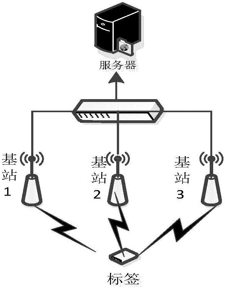
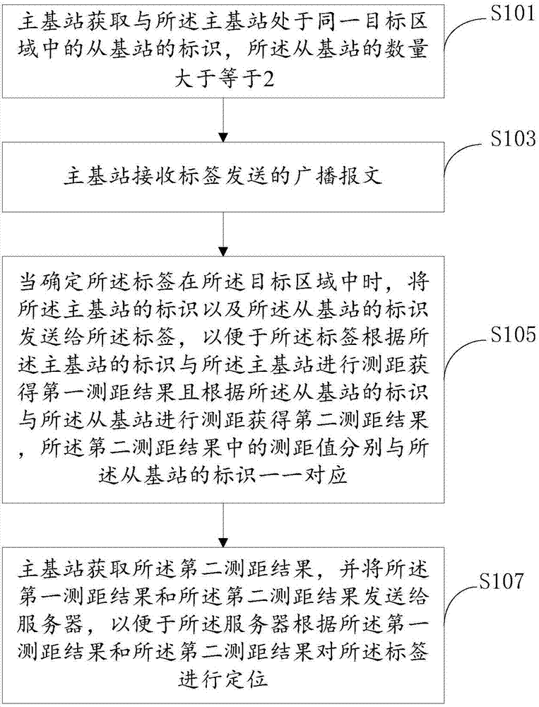
[0058] An embodiment of the present invention provides a method for locating tags in a wireless network, such as figure 2 As shown, including the following steps:
[0059] S101: The master base station acquires the identifiers of the slave base stations in the same target area as the master base station, and the number of the slave base stations is greater than or equal to 2.
[0060] S103: The primary base station receives the broadcast message sent by the tag,
[0061] S105: When it is determined that the tag is in the target area, send the identification of the primary base station and the identification of the secondary base station to the tag, so that the tag can compare with the identification of the primary base station and the The primary base station performs ranging to obtain a first ranging result, and performs ranging with the secondary base station according to the identifier of the secondary base station to obtain a second ranging result. The ranging value in the second ranging result is respectively the same as the One-to-one correspondence between the identifiers of the slave base stations;
[0062] Among them, because the number of slave base stations is greater than or equal to 2, the number of ranging values ​​of the second ranging result of the tag and the slave base station is equal to the number of slave base stations, or if the tag is equal to one of the slave base stations If the ranging is failed, the number of the ranging values ​​of the second ranging result between the tag and the secondary base station is less than the number of secondary base stations. Moreover, the multiple ranging values ​​in the second ranging result will respectively correspond to the identifiers of the secondary base stations corresponding to the ranging in a one-to-one correspondence. In the embodiment of the present invention, the second ranging result may be as shown in Table 1, and 5 secondary base stations respectively correspond to 5 ranging values.
[0063] Secondary base station identification
[0064] Table 1
[0065] S107: The main base station obtains the second ranging result, and sends the first ranging result and the second ranging result to a server, so that the server can use the first ranging result and the The second ranging result locates the tag.
[0066] Optionally, a Slot message is used to send the identification of the primary base station and the identification of the secondary base station to the tag.
[0067] Optionally, in the system used in the embodiment of the present invention, all base stations can be classified into two types: master base stations and slave base stations. The selection of master and slave base stations can be divided into parity or block, similar to the structure of warehouse or room, for example Figure 3A , You can select any one of base station 1, base station 2, base station 3, and base station 4 as the master base station, and the other 3 base stations as slave base stations. In the example, base station 1 is set as the master base station, base station 2, base station 3, and base station 4 For the slave base station. Similar to corridors, roads, tunnels and other structures, for example Figure 3B , Tag 1 and Tag 2 move in the base station, select the odd-numbered base station as the master base station, and the even-numbered base station as the slave base station. The main base station configuration is as follows:
[0068] The base station identifiers in the Slot message returned by the master base station 1 are 1, 2, and 4, where 1 is the master base station itself, and 2, 4 are the slave base stations;
[0069] The base station identifiers in the Slot message from the master base station 3 are 2, 3, 4, and 6, where 3 is the master base station itself, and 2, 4, and 6 are the slave base stations;
[0070] The base station identifiers in the Slot message from the master base station 5 are 4, 5, 6, and 8, where 5 is the master base station itself, and 4, 6, and 8 are the slave base stations;
[0071] The base station identifiers in the Slot message that the master base station 7 replies to are 6, 7, and 8, where 7 is the master base station itself, and 6, and 8 are the slave base stations.
[0072] The beneficial effect of the embodiments of the present invention is that, compared with the existing UWB positioning solution, since the allocation and management of tags are realized at the base station, the shortest possible path is used, and unstable delays and factors are reduced to a minimum. The positioning system is more reliable.
[0073] Optional, such as image 3 As shown, the method further includes:
[0074] S1031: The primary base station determines that the tag is in the target area according to the signal strength value between the tag and the tag acquired when the broadcast message sent by the tag is received.
[0075] Optionally, the step of the primary base station acquiring the identifier of the secondary base station in the same target area as the primary base station specifically includes:
[0076] The primary base station obtains the target area determined by the server according to the tag ranging result collected in the first period T, the identity of the primary base station, and the identity of the secondary base station in the same target area as the primary base station.
[0077] Optional, such as Figure 4 As shown, the method further includes:
[0078] S109: When the server determines that the number of ranging values ​​in the second ranging result is inconsistent with the number of the secondary base stations, the primary base station receives a re-ranging request from the server, and when the tag matches When the signal strength between the primary base stations is greater than or equal to the first threshold, the tag performs distance measurement with the primary base station according to the identifier of the primary base station according to the re-ranging request instruction to obtain a third ranging result and The identifier of the secondary base station and the secondary base station perform ranging to obtain a fourth ranging result, and the ranging values ​​in the fourth ranging result correspond to the identifier of the secondary base station respectively.
[0079] Among them, because the number of slave base stations is greater than or equal to 2, the number of ranging values ​​of the fourth ranging result of the tag and the slave base station is equal to the number of slave base stations, or if the tag is equal to one of the slave base stations If the ranging fails, the number of ranging values ​​of the fourth ranging result between the tag and the secondary base station is less than the number of secondary base stations. In addition, the multiple ranging values ​​in the fourth ranging result correspond to the identifiers of the secondary base stations corresponding to the ranging respectively. In the embodiment of the present invention, the fourth ranging result may be as shown in Table 2. 5 secondary base stations correspond to 4 ranging values ​​respectively, and one secondary base station with a secondary base station identification of 3 fails in ranging, so the ranging value is air.
[0080] Secondary base station identification
[0081] Table 2
[0082] Optional, such as Figure 5 As shown, the method further includes:
[0083] S111: When the server determines that the number of ranging values ​​in the second ranging result is inconsistent with the number of the secondary base stations, the primary base station receives a re-ranging request from the server, and when the tag matches When the signal strength between the primary base stations is less than the first threshold, the base station in the target area adjacent to the target area to which the primary base station belongs is instructed by the re-ranging request to perform ranging on the tag.
[0084] An embodiment of the present invention provides a primary base station for locating tags in a wireless network, such as Image 6 Shown, including:
[0085] The first acquiring module 601 is configured to acquire the identifiers of the secondary base stations in the same target area as the primary base station, and the number of the secondary base stations is greater than or equal to 2;
[0086] The message receiving module 603 is used to receive the broadcast message sent by the tag,
[0087] The first sending module 605 is configured to send the identification of the master base station and the identification of the slave base station to the tag when it is determined that the tag is in the target area, so that the tag is based on the master base station. The identity of the base station performs ranging with the master base station to obtain a first ranging result, and performs ranging with the secondary base station according to the identity of the secondary base station to obtain a second ranging result. The measurement in the second ranging result The distance values ​​correspond to the identifiers of the secondary base stations respectively;
[0088] The second obtaining module 607 is configured to obtain the second ranging result,
[0089] The second sending module 609 is configured to send the first ranging result and the second ranging result to a server, so that the server can pair the first ranging result with the second ranging result The label is positioned.
[0090] The beneficial effect of the embodiments of the present invention is that, compared with the existing UWB positioning solution, since the allocation and management of tags are realized at the base station, the shortest possible path is used, and unstable delays and factors are reduced to a minimum, so that The positioning system is more reliable.
[0091] Optional, such as Figure 7 As shown, the main base station further includes:
[0092] The tag detection module 611 is configured to determine that the tag is in the target area according to the signal strength value between the tag and the tag acquired when the broadcast message sent by the tag is received.
[0093] Optionally, the first obtaining module 601 is specifically configured to:
[0094] Obtain the target area determined by the server according to the tag ranging result collected in the first period T, the identifier of the primary base station, and the identifier of the secondary base station in the same target area as the primary base station.
[0095] Optional, such as Picture 8 As shown, the main base station further includes:
[0096] The first request receiving module 613 is configured to receive a re-ranging request from the server when the server determines that the number of ranging values ​​in the second ranging result is inconsistent with the number of the secondary base stations,
[0097] The first indicating module 615 is configured to instruct the tag according to the re-ranging request according to the identification of the primary base station and the identification of the primary base station when the signal strength between the tag and the primary base station is greater than or equal to a first threshold. The primary base station performs ranging to obtain a third ranging result, and performs ranging with the secondary base station according to the identifier of the secondary base station to obtain a fourth ranging result. The ranging value in the fourth ranging result is respectively the same as the There is a one-to-one correspondence between the identifiers of the slave base stations.
[0098] Optional, such as Picture 9 As shown, the main base station further includes:
[0099] The second request receiving module 617 is configured to: when the server determines that the number of ranging values ​​in the second ranging result is inconsistent with the number of the secondary base stations, the primary base station receives the re-ranging of the server request,
[0100] The second indication module 619 is configured to indicate the target area adjacent to the target area to which the main base station belongs according to the re-ranging request when the signal strength between the tag and the main base station is less than a first threshold The base station in, performs ranging on the tag.
[0101] The present invention is described with reference to flowcharts and/or block diagrams of methods, devices (systems), and computer program products according to embodiments of the present invention. It should be understood that each process and/or block in the flowchart and/or block diagram, and the combination of processes and/or blocks in the flowchart and/or block diagram can be implemented by computer program instructions. These computer program instructions can be provided to the processor of a general-purpose computer, a special-purpose computer, an embedded processor, or other programmable data processing equipment to generate a machine, so that the instructions executed by the processor of the computer or other programmable data processing equipment can be generated In the process Figure one Process or multiple processes and/or boxes Figure one A device with functions specified in a block or multiple blocks.
[0102] These computer program instructions can also be stored in a computer-readable memory that can guide a computer or other programmable data processing equipment to work in a specific manner, so that the instructions stored in the computer-readable memory produce an article of manufacture including the instruction device. The device is implemented in the process Figure one Process or multiple processes and/or boxes Figure one Functions specified in a box or multiple boxes.
[0103] These computer program instructions can also be loaded on a computer or other programmable data processing equipment, so that a series of operation steps are executed on the computer or other programmable equipment to produce computer-implemented processing, so as to execute on the computer or other programmable equipment. Instructions are provided to implement the process Figure one Process or multiple processes and/or boxes Figure one Steps of functions specified in a box or multiple boxes.
[0104] Finally, it should be noted that the above embodiments are only used to illustrate the technical solutions of the present invention, not to limit it; although the present invention has been described in detail with reference to the foregoing embodiments, those of ordinary skill in the art should understand that: The technical solutions recorded in the foregoing embodiments are modified, or some of the technical features are equivalently replaced; these modifications or replacements do not cause the essence of the corresponding technical solutions to deviate from the spirit and scope of the technical solutions of the embodiments of the present invention.

PUM

no PUM

Description & Claims & Application Information

We can also present the details of the Description, Claims and Application information to help users get a comprehensive understanding of the technical details of the patent, such as background art, summary of invention, brief description of drawings, description of embodiments, and other original content. On the other hand, users can also determine the specific scope of protection of the technology through the list of claims; as well as understand the changes in the life cycle of the technology with the presentation of the patent timeline. Login to view more.

Similar technology patents

Computer-controlled expansion accumulative lifting method for erecting super-high arch grid structure

ActiveCN104947942AReduce construction costsThe construction period is highly controllableArched structuresVaulted structuresEngineeringComputational analysis
Owner:浙江东南网架股份有限公司

Classification and recommendation of technical efficacy words

  • Reduce construction costs
  • Flexible layout

Automatic container system

InactiveCN103738640AFlexible layoutComfortable shopping experienceStorage devicesTruckStandard cell
Owner:潘玉坤 +1
Why Eureka
Try Eureka