
Aluminum electrolysis flue gas desulfurization device and desulfurization method

A desulfurization device, electrolytic aluminum technology, applied in separation methods, chemical instruments and methods, gas treatment, etc., can solve the problems of not having the conditions for desulfurization of seawater, and achieve the effects of broad market application prospects, short process flow, and strong applicability

Inactive Publication Date: 2017-10-10
SHENYANG ALUMINIUM MAGNESIUM INSTITUTE
View PDF15 Cites 2 Cited by
  • Summary
  • Abstract
  • Description
  • Claims
  • Application Information

AI Technical Summary

Problems solved by technology

However, due to electricity price factors, domestic electrolytic aluminum plants generally build electrolytic aluminum plants inland where electricity costs are low, and do not have the conditions for seawater desulfurization

Method used


Image

  • Aluminum electrolysis flue gas desulfurization device and desulfurization method
  • Aluminum electrolysis flue gas desulfurization device and desulfurization method

Examples


Embodiment 1

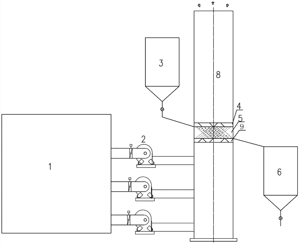
[0029] Such as figure 1 As shown in , an electrolytic aluminum flue gas desulfurization device, the flue gas from the electrolytic aluminum flue gas dry process system 1 is connected to the fluidized boiling box 5, and the flue gas from the fluidized boiling box 5 is discharged through the chimney 8 . The flue gas from the electrolytic aluminum flue gas dry process system is sent to the fluidized boiling box through the main induced draft fan 2, and the fluidized boiling box 5 is provided with an adsorbent. The fluidized boiling box 5 is arranged in the middle of the chimney 8, the main induced draft fan 2 sends the flue gas from the electrolytic aluminum flue gas dry process system 1 to the lower part of the chimney 8, and the fluidized boiling box 5 feed inlet is set at The upper part communicates with the fresh feed bin 3 , and the outlet of the fluidized boiling box 5 is located in the lower part and communicates with the reaction feed bin 6 . The bottom of the fluidized...

Embodiment 2

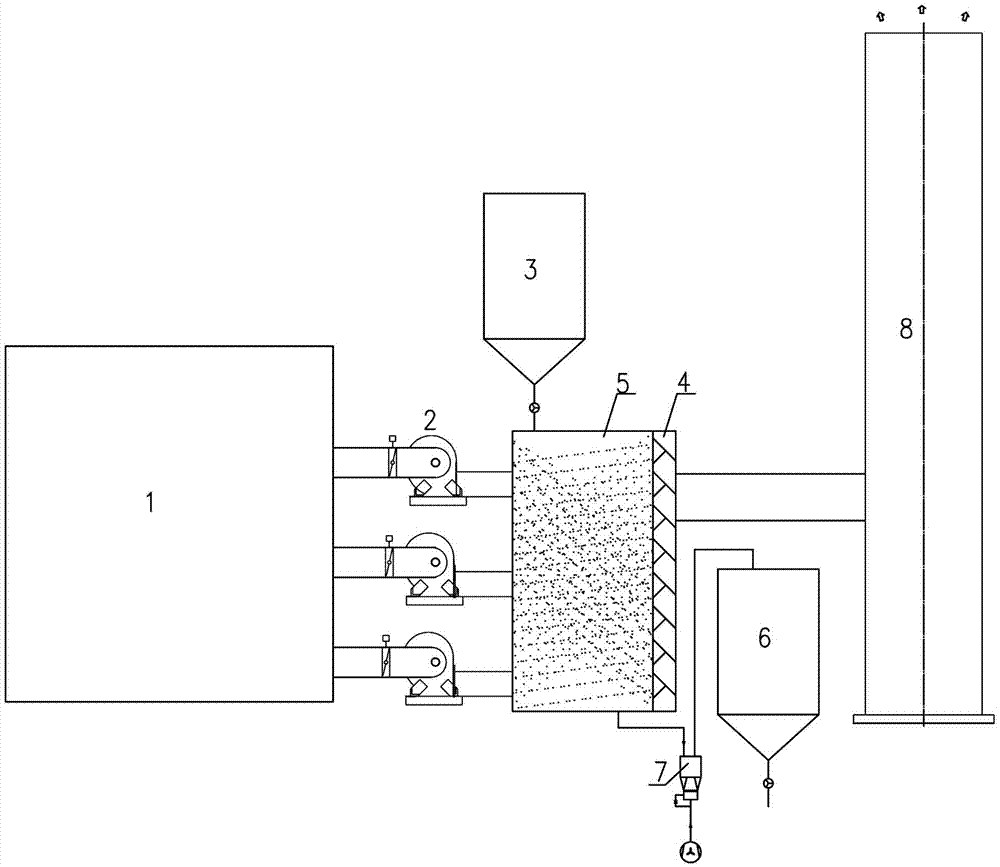
[0032] The fluidized boiling tank in Example 1 is arranged between the main induced draft fan and the chimney. The smoke inlet of the fluidized boiling box is connected with the main induced draft fan, and the smoke outlet of the fluidized boiling box is connected with the chimney; The outlet of the boiling box is located at the bottom and communicates with the reaction silo, the outlet of the fluidized boiling box is connected with the reaction silo through the material conveying system, and a filter screen is installed on the side of the fluidized boiling box smoke outlet mesh; alkaline particles are Ca(OH) 2 , other with embodiment 1.

Embodiment 3

[0034] The basic particle in embodiment 2 is MgCO 3 , other with embodiment 2.


PUM


Abstract

The invention relates to a desulfurization device and a desulfurization method, particularly relates to an aluminum electrolysis flue gas desulfurization device and desulfurization method, and is mainly used for electrolysis flue gas desulfurization in the aluminum electrolysis industry. Flue gas coming from an aluminum electrolysis flue gas dry method system is connected to a fluidization and boiling tank body, and the flue gas coming from the fluidization and boiling tank body is discharged from a chimney. The advantages and the effects of the desulfurization device and the desulfurization method are as follows: SO2 in the flue gas is adsorbed by an adsorbent in the fluidization and boiling tank body; a filter screen can filter out particles in the flue gas; a fresh material bin can be used for adsorbent supplementing, and a reaction material bin stores the reacted adsorbent; the addition amount and the addition speed of the adsorbent are regularly regulated according to the concentration of SO2 at the outlet of the chimney; the filter screen is regularly cleaned or replaced to avoid the increase of system resistance; the adsorbed particles are delivered into a reaction storage bin through a delivery system; and the desulfurization device and the desulfurization method have the advantages of short flow, high efficiency, small occupied area, low energy consumption, small maintenance quantity, high control degree and the like.

Description

technical field [0001] The invention relates to a desulfurization device and a desulfurization method, in particular to an electrolytic aluminum flue gas desulfurization device and a desulfurization method, which are mainly used in electrolytic flue gas desulfurization in the electrolytic aluminum industry. Background technique [0002] In the electrolytic aluminum industry, the aluminum electrolysis process uses the alumina melt as the electrolyte and the carbon material as the electrode for electrolysis. Liquid metal aluminum is precipitated on the cathode, and CO is produced on the anode. 2 the main anode gas. At the same time, because the carbon block contains S element, the electrolysis flue gas contains not only hydrogen fluoride, fluoride, dust, but also SO 2 . According to the calculation of SO in general electrolysis flue gas 2 The concentration is 200-300mg / Nm 3 . [0003] According to the "Aluminum Industry Pollutant Discharge Standard" (GB25465-2010) and the...

Claims


Application Information

Patent Timeline
Patent Type & Authority Applications(China)
IPC IPC(8): B01D53/83B01D53/86B01D53/50B01D46/10
CPCB01D46/10B01D53/508B01D53/8609B01D2251/304B01D2251/402B01D2251/404B01D2251/604B01D2251/606B01D2255/20738B01D2255/20753B01D2255/70B01D2258/025
Inventor 宋海琛杨晓东刘雅锋周东方胡红胜
Owner SHENYANG ALUMINIUM MAGNESIUM INSTITUTE
Learn More