Technology method for improving angle cutting quality of equal angle steel
A technology of equilateral angle steel and process method, which is applied in the direction of manufacturing tools, metal processing equipment, metal processing machinery parts, etc., can solve the problems that the edge distance of the cut corner does not meet the process regulations, reduce the quality of the angle steel incision, etc., so as to avoid movement and improve The effect of cutting corner quality and avoiding the number of rework
- Summary
- Abstract
- Description
- Claims
- Application Information
AI Technical Summary
Problems solved by technology
Method used
Image
Examples
Embodiment 1
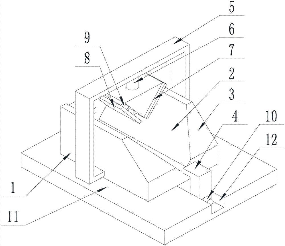
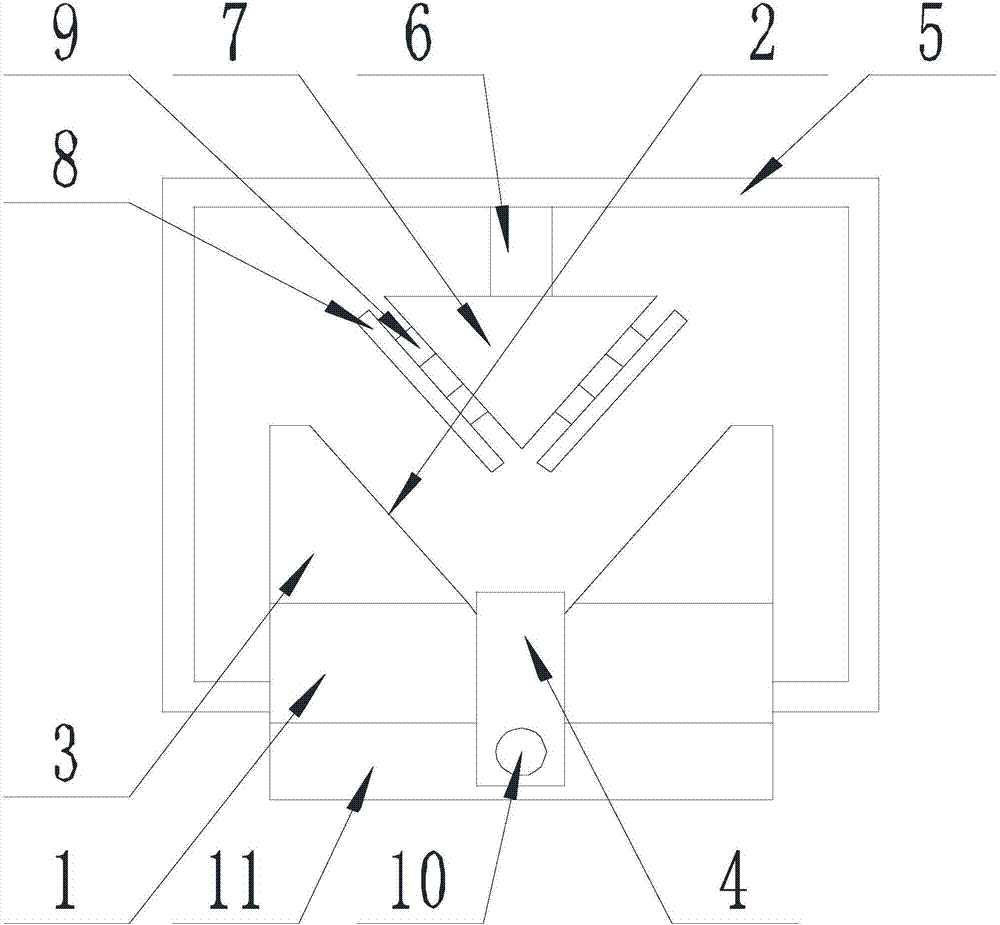
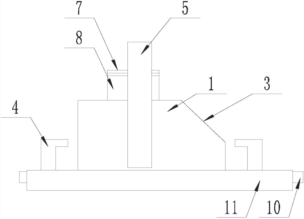
[0039] Such as Figure 1-Figure 4 Shown, the processing method that the present invention improves equilateral angle steel angle cutting quality, comprises the steps:
[0040] Step A Preparation: According to the requirements of the drawings, select the appropriate angle steel angle cutting machine;
[0041] Step B installation: fix the fixed block 1 on the workbench of the angle cutter;
[0042] Step C numbering material: numbering the angle steel to be cut, and drawing the angle cutting line on the angle steel;
[0043] Step D Placement: Place the angle steel in the V-shaped through groove 2 arranged on the upper surface of the fixed block 1, and make the corner to be cut off on the angle steel be located at the place where the right angle 3 is inverted on the through groove 2, and the angle cutting line is located at the inverted The right angle 3 is away from the side of the through groove 2, the included angle of the angle steel is in contact with the angle between the ...
Embodiment 2
[0049] The present invention is based on embodiment 1, and the present invention is further described.
[0050] Such as Figure 1-Figure 4 As shown, the process method for improving the quality of equilateral angle steel corner cutting in the present invention is provided with a gantry 5 on the fixed block 1, the gantry surface of the gantry 5 is perpendicular to the axis of the through groove 2, and the door shape One end of frame 5 is connected with the side wall of fixed block 1, and the other end of gantry 5 is connected with the other side wall of fixed block 1;
[0051] The top of the inner wall of the gantry 5 is provided with a pneumatic cylinder 6 whose axis is perpendicular to the axis of the through groove 2, the cylinder bottom of the pneumatic cylinder 6 is connected with the gantry 5, and the end of the piston rod of the pneumatic cylinder 6 faces the through groove 2 .
[0052] When the angle steel cuts corners, the piston rod of the pneumatic cylinder 6 stret...
Embodiment 3
[0056] The present invention is based on embodiment 2, and the present invention is further described.
[0057] Such as Figure 1-Figure 4 As shown, the present invention improves the quality of equilateral angle steel corner cutting. A moving assembly is provided on the side wall of the fitting bar 7 that can be in contact with the groove wall of the through groove 2. The moving assembly includes a moving plate 8 And the spring 9, the moving plate 8 is connected with the corresponding side wall on the fitting bar 7 through the spring 9, and the moving plate 8 is parallel to the corresponding side wall on the fitting bar 7, and the spring 9 is a helical cylindrical spring, which The axis is perpendicular to the mobile plate 8 .
[0058] When the machine is in transmission, it will vibrate, and the farther away from the transmission, the greater the vibration amplitude. Therefore, in order to further reduce the vibration of the angle steel during corner cutting, a moving asse...
PUM
 Abstract
Description
Claims
Application Information
 - R&D
- Intellectual Property
- Life Sciences
- Materials
- Tech Scout
- Unparalleled Data Quality
- Higher Quality Content
- 60% Fewer Hallucinations
Browse by: Latest US Patents, China's latest patents, Technical Efficacy Thesaurus, Application Domain, Technology Topic, Popular Technical Reports.
© 2025 PatSnap. All rights reserved.Legal|Privacy policy|Modern Slavery Act Transparency Statement|Sitemap|About US| Contact US: help@patsnap.com


