Paper-making wastewater treatment equipment

A technology for treating equipment and papermaking wastewater, which is applied in processing wastewater treatment, multi-stage water treatment, water/sewage treatment, etc. It can solve the problems of large investment, large amount of wastewater discharge, and many suspended fibers, and save water resources. , improve the utilization rate, improve the effect of water quality

Inactive Publication Date: 2017-10-20
ANHUI GUONENG YISHENG ENVIRONMENTAL PROTECTION SCI & TECH
View PDF5 Cites 0 Cited by
  • Summary
  • Abstract
  • Description
  • Claims
  • Application Information

AI Technical Summary

Problems solved by technology

[0002] With the increase of paper production and consumption, the water consumption and wastewater discharge of the paper industry have also increased. In the world, the water pollution control of the paper industry has become a focus of attention of the paper industry and the whole society, and it is also the survival and development of the paper industry. The key point is that the paper industry is one of the industries with large investment, high energy consumption, and serious environmental pollution. Its pollution is characterized by large wastewater discharge, high chemical oxygen demand, and a lot of fiber suspended matter in wastewater. Currently, wastewater treatment in paper mills is based on biological Treatment is the main method, but the COD removal rate of the biological treatment method is generally about 60%. If the COD reaches the standard, a tertiary treatment is required to make the water quality meet the requirements, and there will be a large amount of pulp fibers in the wastewater. If the pulp fibers are not recycled, there will be A large amount of pulp enters the wastewater treatment system, which seriously affects the treatment effect of the wastewater treatment system and causes waste of pulp. Therefore, it is necessary to invent a papermaking wastewater treatment equipment to solve the above problems

Method used


Image

  • Paper-making wastewater treatment equipment
  • Paper-making wastewater treatment equipment
  • Paper-making wastewater treatment equipment

Examples


Embodiment Construction

[0015] The following will clearly and completely describe the technical solutions in the embodiments of the present invention with reference to the accompanying drawings in the embodiments of the present invention. Obviously, the described embodiments are only some, not all, embodiments of the present invention. Based on the embodiments of the present invention, all other embodiments obtained by persons of ordinary skill in the art without making creative efforts belong to the protection scope of the present invention.

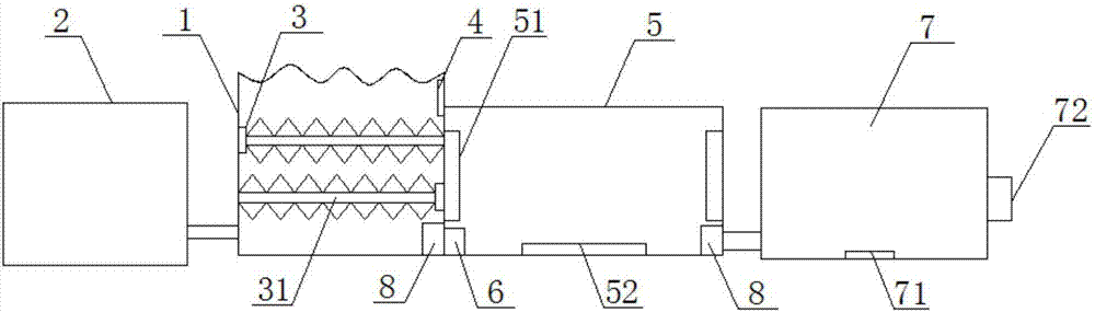
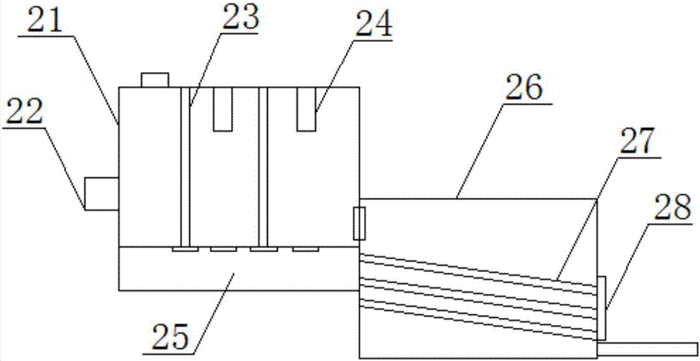
[0016] The present invention provides such Figure 1-3 The shown papermaking wastewater treatment equipment includes an aeration tank 1, a wastewater pretreatment device 2 is provided on one side of the aeration tank 1, and a motor casing 3 is provided on one side of the inner wall of the aeration tank 1. A motor is provided inside the motor housing 3, and a rotating shaft 31 is provided on one side of the motor housing 3, and the rotating shaft 31 is connecte...


PUM


Abstract

The invention discloses paper-making wastewater treatment equipment which comprises an aeration tank. A wastewater pretreatment device is arranged on one side of the aeration tank, a motor shell is arranged on one side of the inner wall of the aeration tank, a motor is arranged in the motor shell, a rotating shaft is arranged on one side of the motor shell, the rotating shaft is in transmission connection with a motor output shaft, an air compressor is arranged on one side of the aeration tank, and a wastewater treatment tank is arranged on one side of the aeration tank. By the arrangement, pulp fiber in the wastewater generated from the paper-making process can be filtered and recycled, utilization rate of paper pulp is increased, and cost in wastewater treatment is saved; by the arrangement of the air compressor and the rotating shaft, a certain concentration of dissolved oxygen in water can be sustained, and impurities in the wastewater stay suspended all along; the wastewater adjusted in PH value and color through a purification tank is enabled to meet emission standard, and lots of water resources are saved.

Description

technical field [0001] The invention relates to the field of sewage treatment, in particular to a papermaking wastewater treatment equipment. Background technique [0002] With the increase of paper production and consumption, the water consumption and wastewater discharge of the paper industry have also increased. In the world, the water pollution control of the paper industry has become a focus of attention of the paper industry and the whole society, and it is also the survival and development of the paper industry. The key point is that the paper industry is one of the industries with large investment, high energy consumption, and serious environmental pollution. Its pollution is characterized by large wastewater discharge, high chemical oxygen demand, and a lot of fiber suspended matter in wastewater. Currently, wastewater treatment in paper mills is based on biological Treatment is the main method, but the COD removal rate of the biological treatment method is generall...

Claims


Application Information

Patent Timeline
Patent Type & Authority Applications(China)
IPC IPC(8): C02F9/14C02F103/28
CPCC02F1/001C02F1/5281C02F1/66C02F1/725C02F1/78C02F3/02C02F9/00C02F2103/28C02F2301/08
Inventor 钟华梁明张兵
Owner ANHUI GUONENG YISHENG ENVIRONMENTAL PROTECTION SCI & TECH
Why Eureka
Try Eureka