Chain multi-port gird-connected interface device and control method

A technology of interface device and control method, applied in circuit devices, output power conversion devices, AC network circuits, etc., can solve the problems of low cost performance, complex structure, low reliability, etc., to maximize equipment utilization and flexible configuration , the effect of high reliability

Active Publication Date: 2017-10-20
NR ELECTRIC CO LTD +1
View PDF4 Cites 26 Cited by
  • Summary
  • Abstract
  • Description
  • Claims
  • Application Information

AI Technical Summary

Problems solved by technology

The main disadvantages of this structure are: (1) The structure is complex: Figure 1-8 The main function of the converter is to provide the DC bus port. The converter itself is very complex, and the subsequent stage of the chain structure requires a large number of DC / DC converters. The output side of the converter is directly connected in parallel, and the control complexity is high. Low-voltage The AC bus port is converted from the DC bus port. The power comes from the DC bus, which occupies the power consumption capacity of the DC bus. The AC and DC power consumption is not completely decoupled, which also increases the difficulty of coordinated control. (2) There are many links , low efficiency: Efficiency is a key indicator of power electronic equipment, Figure 1-8 There are multiple links in the structure of the power electronic converter, and the overall efficiency of the equipment is low
(3) Low reliability of equipment: the latter stage of the chain structure requires a large number of DC / DC converters, and the output side of the converters is connected in parallel, which is not conducive to fault isolation. Once the low-voltage DC bus fails, it will affect all the DC / DC converters of the previous stage. DC converter and subsequent DC / AC inverter
[0003] The essential defect of the existing technology is that the port is single, and the use of a single port to be compatible with various types of units leads to high complexity and low cost performance; the above-mentioned solutions all have a DC bus, which makes it difficult to isolate faults and has low reliability

Method used


Image

  • Chain multi-port gird-connected interface device and control method
  • Chain multi-port gird-connected interface device and control method
  • Chain multi-port gird-connected interface device and control method

Examples


Embodiment Construction

[0056] The technical solutions of the present invention will be described in detail below in conjunction with the accompanying drawings.

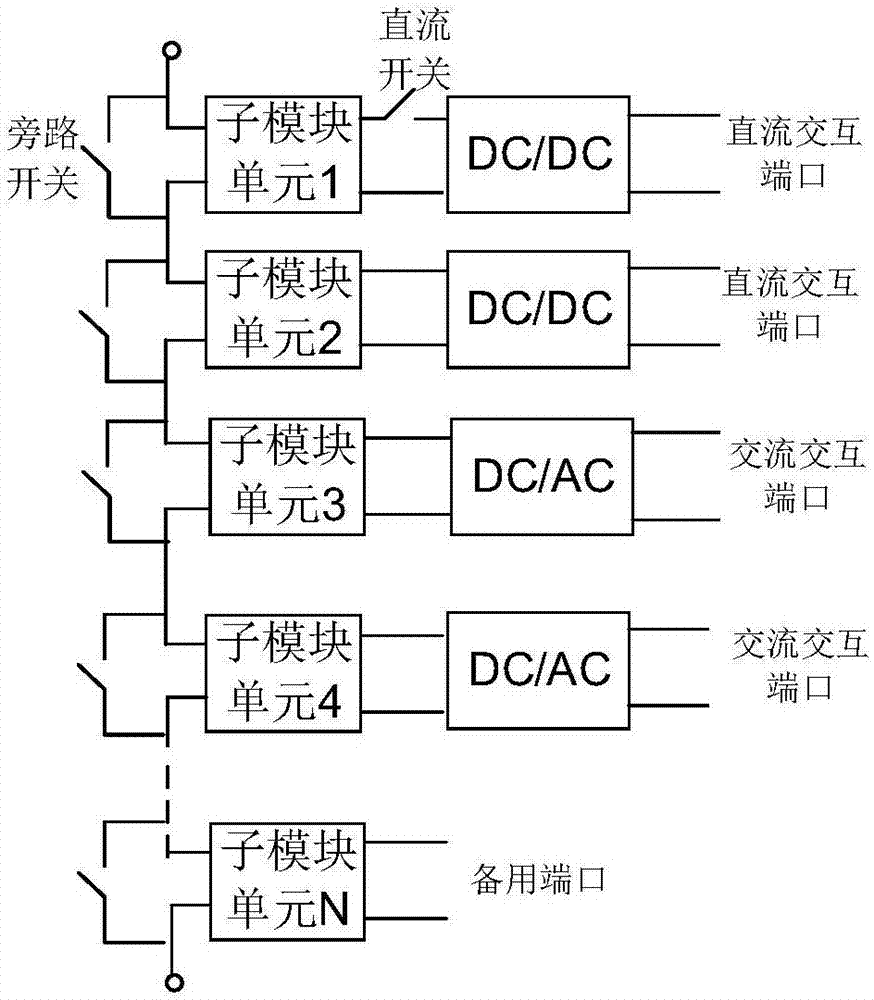
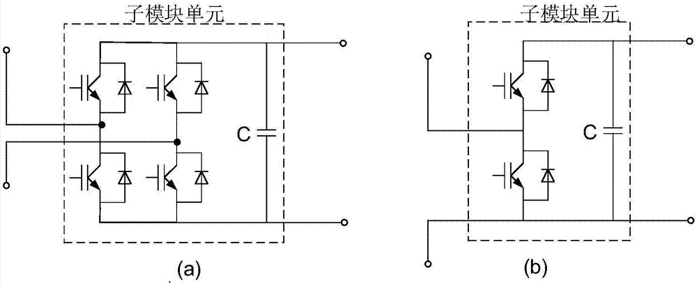
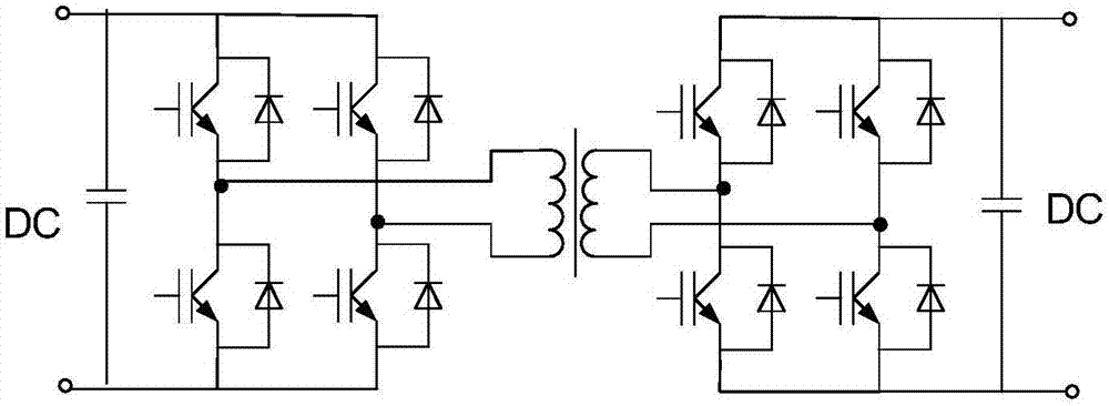
[0057] Such as figure 1 Shown: a chain-type multi-port grid-connected interface device, including a commutation chain, the commutation chain is composed of at least two sub-module units connected in series, and the sub-module units include power conversion units and capacitors. The positive pole and negative pole lead out are defined as the DC terminal of the sub-module unit. One end of the power conversion unit is connected in parallel with the capacitor, and the other end is defined as the AC terminal of the sub-module unit. The AC terminals of each sub-module are connected in sequence. The chain The multi-port grid-connected interface device also includes at least one DC converter and at least one DC-AC converter. The DC converter can convert one type of DC power into another DC power with different output characteristics. One end of th...


PUM


Abstract

The invention discloses a chain multi-port grid-connected interface device comprising a commutation chain. The commutation chain is formed by at least two submodule units connected in series in the same direction. The chain multi-port grid-connected interface device further comprises at least one DC converter and at least one DC-AC converter. One end of each DC converter is connected with a DC end of the corresponding submodule unit, and the other end of the DC converter is defined as a DC interaction port of the grid-connected interface device. A DC connection end of each DC-AC converter is connected with a DC end of the corresponding submodule unit, and an AC connection end of the DC-AC converter is defined as an AC interaction port of the grid-connected interface device. The invention also includes a control method using the above chain multi-port grid-connected interface device. The chain multi-port grid-connected interface device of the invention provides the plurality of independent ports for the connection with a low-voltage power supply, a load and an energy storage unit and achieves plug and play, thereby greatly reducing the implementation difficulty and cost.

Description

technical field [0001] The invention belongs to the field of power electronic converters, in particular to a multi-port grid-connected interface device with a chain structure and a control method. Background technique [0002] In recent years, with the continuous advancement of distributed power generation technology and the increasingly mature power electronics technology, distributed power generation has become more and more widely used in power grids, and has gradually become an effective supplement to large power grids. The composition of distributed power generation, loads and energy storage devices Microgrid, many distributed power sources, loads, and energy storage devices are of different types, including DC or AC, and the voltage level and capacity are also different. How to economically and effectively connect the above units and conduct unified management is a difficult problem to solve . The technical solutions disclosed in the prior art include the following, p...

Claims


Application Information

Patent Timeline
Patent Type & Authority Applications(China)
IPC IPC(8): H02J3/38
CPCH02J2300/28H02J3/381H02J2300/24Y02E10/56H02J2310/10H02J2300/40H02M3/33584H02M7/5387H02M1/0074H02M1/008H02M7/4835H02M1/0095H02M3/33507H02M7/493H02M3/33576H02M7/53871
Inventor 谢晔源王宇李海英连建阳张中锋田杰
Owner NR ELECTRIC CO LTD
Why Eureka
Try Eureka