Electric railway energy storage power supply device and control method thereof

A technology for electrified railways and power supply devices, which is applied in the direction of AC network load balancing, AC networks with the same frequency from different sources, etc., and can solve incorrect criteria, failure of energy storage and peak shaving work, incorrect criterion methods, etc. problems, to achieve good stability and accuracy, improve technical performance, and technologically advanced effects

Active Publication Date: 2017-10-24
SOUTHWEST JIAOTONG UNIV
View PDF10 Cites 6 Cited by
  • Summary
  • Abstract
  • Description
  • Claims
  • Application Information

AI Technical Summary

Problems solved by technology

"But, the problem that this technical scheme exists is: (1) when active current Ip<0, carry out energy storage (see its claim 5 and accompanying drawing 5) criterion and there is incorrect situation
For example, the Beijing-Shanghai high-speed railway has a total length of 1318km, 24 stations, and 27 substations (54 power supply arms). The average distance between stations (about 55km) is much greater than the average length of power supply arms (about 24.4km). The vehicle (electrical) braking occurs when the station is stopped. Obviously, because there is a high probability of no power supply arm at the station, then the probability of no electric braking is high, or even if the braking occurs, its regenerative power is used by the same traction train If the electric braking power is not absorbed by the same train, the criterion in this case will not occur; furthermore, even if the electric braking power is not absorbed by the same train, it will It returns to the grid without adding any equipment, which is the most direct and economical, and is also encouraged by the state for energy conservation and emission reduction (just like household photovoltaic power generation). This patent specifically sets the energy storage device when the power current Ip<0 There is no need for energy storage
(2) The patent uses "total current I s >Rated current I of the connected supply arm e "(see claim 7) is also incorrect
In short, this technical solution has the failure of energy storage and peak shaving. At this time, it is impossible to "reduce the installed capacity and billing capacity of the traction transformer and save costs", and it is impossible to achieve real-time peak shaving under all working conditions. Valley filling optimization

Method used


Image

  • Electric railway energy storage power supply device and control method thereof
  • Electric railway energy storage power supply device and control method thereof
  • Electric railway energy storage power supply device and control method thereof

Examples


Embodiment

[0020] The present invention will be further described below in conjunction with accompanying drawing:

specific Embodiment approach

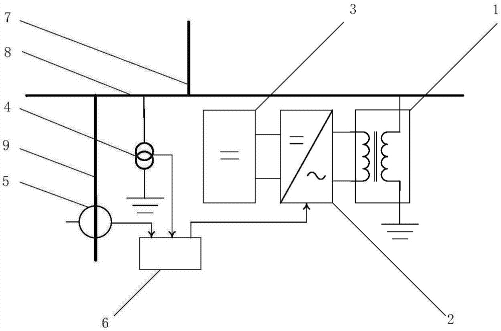
[0021] figure 1 As shown, a specific embodiment of the present invention is: an electrified railway energy storage power supply device, including a coupling transformer 1, an AC-DC converter 2, an energy storage device 3, a voltage transformer 4, a current transformer 5 and a measurement and control unit 6. Take the high-speed railway traction substation as an example, in which the secondary side of the main transformer with single-phase connection leads to the traction incoming line 7, and the traction incoming line 7 is connected to the traction busbar 8; the traction busbar is connected to the traction network through the feeder line 9 to supply power to the train; the voltage transformer 5 Measure the voltage of the traction bus 8 to ground; the current transformer 5 measures the traction load of the feeder 9; The port is connected to the energy storage device 3; the measuring end of the voltage transformer 4 and the measuring end of the current transformer 5 are connected...


PUM


Abstract

The invention provides an electric railway energy storage power supply device and a control method thereof, and relates to the field of electric railway traction power supply. A traction inlet wire is connected with a traction bus; the traction bus is connected with a traction network through a feeder line so as to supply power to a train; the primary side of a coupling transformer is connected with the traction bus and the ground, and the secondary side thereof is connected with the AC port of an AC-DC converter; the DC port of the AC-DC converter is connected with an energy storage device; a measurement and control unit is connected with the measuring ends of a voltage transformer and a current transformer and the control end of the AC-DC converter. The control method comprises the steps of selecting a reference value which is greater than or equal to an average load value by regarding load peak clipping as a target; enabling the maximum power of the energy storage device to be equal to the maximum value of a former peak, and enabling the capacity of the energy storage device to be equal to the area of the former peak with the biggest area; when the traction load power is less than the reference value, enabling the AC-DC converter to be in a rectification working condition and charging the energy storage device; and when the traction load power is greater than the reference value, enabling the AC-DC converter to be in an inversion working condition and discharging the energy storage device, and feeding the inverted AC power into the traction bus. The electric railway energy storage power supply device and the control method thereof are used for peak-clipping power supply and negative sequence management.

Description

technical field [0001] The invention relates to the field of electrified railway traction power supply, in particular to the management and control technology of electrified railway traction load load shifting and valley filling. Background technique [0002] Peak shaving and valley filling are important measures for power system load management. For the power grid, peak shaving is conducive to improving the utilization rate of power transmission and transformation equipment, saving equipment expansion and updating costs, and reducing power supply costs. For ordinary users, it can use The peak-to-valley price difference achieves the economic benefit of reducing electricity bills. The energy storage system has the dual functions of electric energy storage and release, that is, it has the dual functions of load shaving and valley filling. Among them, the battery energy storage system, the supercapacitor energy storage system and its hybrid energy storage system have unique adv...

Claims


Application Information

Patent Timeline
Patent Type & Authority Applications(China)
IPC IPC(8): H02J3/06H02J3/32
CPCH02J3/06H02J3/32
Inventor 赵艺李子晗李群湛解绍锋郭锴黄小红
Owner SOUTHWEST JIAOTONG UNIV
Why Eureka
Try Eureka