
A speed regulation method for fans of subway energy-feedback devices based on power prediction

A fan speed regulation and power prediction technology, which is applied to components of pumping devices for elastic fluids, pump devices, mechanical equipment, etc., can solve the problems of large temperature rise difference of electronic components, fan oscillation, and IGBT power device service life Influence and other problems, to achieve the effect of low temperature rise and change, reduce fan power loss, and ensure long-term safe operation of the device

Active Publication Date: 2020-11-27
NANJING APAITEK TECH
View PDF6 Cites 0 Cited by
  • Summary
  • Abstract
  • Description
  • Claims
  • Application Information

AI Technical Summary

Problems solved by technology

However, the operation of the fan will also bring noise pollution and power loss. At present, the efficiency of a good converter in the market is basically about 98%, and the energy-feeding device needs to run 24 hours without stopping, which brings power consumption and noise pollution. is worthy of our attention
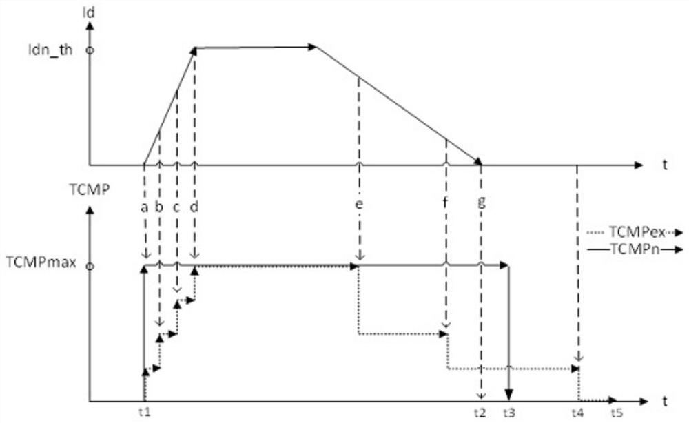
[0003] The solution to fan noise pollution and power loss is generally to use intelligent wind speed regulation, but the traditional fan speed regulation is flawed for subway trains, where the load changes rapidly, and the braking instantaneous power reaches the maximum, such as figure 1 As shown, the dotted line TCMPex is the traditional speed regulation method. After the process of a, b, c, and d, the fan cannot be adjusted to the maximum until the maximum current is detected (point d), which leads to a large difference in the temperature rise of the fan , has an impact on the service life of the IGBT power device. How to obtain the reference current corresponding to the speed in advance so as to reduce the difference in the sudden increase in the temperature of the power device is the key to solving this problem.
In addition, the traditional wind speed adjustment is completely defined according to the current reference and temperature. When the current decreases, the fan reference speed will change with the current. Lowering the temperature to the set threshold can reduce the time for the fan to run, figure 1 From t1 to t4, the shorter the train braking period, the longer the noise pollution time of the fan, and when it oscillates frequently or near the threshold temperature, the adjustment of the fan speed will cause speed oscillation, which is easy to generate new fan noise and affect The life of the fan is also very complicated to control
[0004] The existing public technologies include: Patent No. CN 109098999 A A method and control device for controlling the fan speed of electronic equipment through real-time acquisition of the ambient temperature and the temperature of electronic components to dynamically adjust the fan speed to solve the problem of fan speed adjustment in the existing fan speed regulation technology Fan noise, increased energy consumption or untimely heat dissipation of electronic equipment caused by untimely problems, and the speed adjustment process is smooth and vibration-free, but there is no advance link for the reference speed of wind speed adjustment. When used, the temperature rise difference of electronic components is relatively large; patent number CN 106979169 A is a fan control method and equipment, through the setting of the temperature threshold and the adjustment of the speed, the noise of the equipment is greatly reduced, and the temperature can be better guaranteed. Rising rate, but this method of adjustment is more complicated, and the adjustment is too frequent for high-power fans commonly used in energy-feeding devices, which may cause fan oscillation

Method used


Image

  • A speed regulation method for fans of subway energy-feedback devices based on power prediction
  • A speed regulation method for fans of subway energy-feedback devices based on power prediction

Examples


Embodiment Construction

[0024] The present invention will be specifically described below in conjunction with the accompanying drawings.

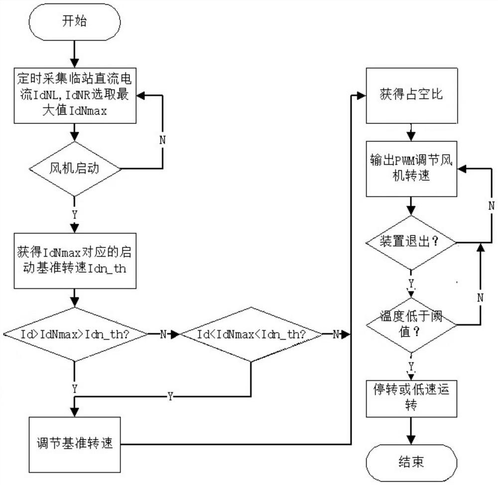
[0025] as attached figure 1 , 2 As shown, a method for adjusting the speed of a fan in a subway energy-feed device based on power prediction is characterized in that it includes the following steps:

[0026] Step 1: Collect and select the maximum power value of the feedback peak power of the subway energy feedback device on the adjacent platform in the previous braking period, and predict the peak feedback power of the platform in this braking period according to the power value to obtain The base value of the predicted power corresponding to the current is obtained, and the base value of the predicted power corresponding to the current is compensated and adjusted according to the output current of the subway energy feeder device collected in real time at the station.

[0027] Step 2: When the subway energy feedback device starts to start the brake feedback, the...


PUM


Abstract

The invention relates to a subway energy feedback device draught fan speed regulation method based on power prediction. The subway energy feedback device draught fan speed regulation method based on the power prediction includes following steps: step 1, obtaining reference value of current corresponding to predicted power according to current corresponding to the maximum power value of feedback peak power, collected on an adjacent station platform in the last period, of a subway energy feedback device, and performing compensation and regulation on the reference value of the current corresponding to the predicted power according to output current, collected by a current station platform in real time, of the subway energy feedback device; and step 2, beginning to start a draught fan, starting the draught fan by adopting rotation speed corresponding to the predicted power current reference value, then compensating and regulating the reference current, completing regulation until the subway energy feedback device outputs the maximum peak current, keeping stable output of the rotation speed of the draught fan, setting temperature to be lower than preset quit threshold value, regulatingthe rotation speed of the draught fan, and reducing the rotation speed of the draught fan until the draught fan rotates at the low speed or stops running. The subway energy feedback device draught fanspeed regulation method is simple to operate in the whole process, does not need to frequently regulate the draught fan, and guarantees that temperature variation difference of power devices is reduced under the working condition that subway braking has strong periodicity and large power sudden change.

Description

technical field [0001] The invention relates to the technical field of power electronics, in particular to a method for adjusting the speed of a fan in a subway energy-feedback device based on power prediction. Background technique [0002] Subway energy-feedback device is an energy-saving device that is used to absorb and feed energy back to the grid for reuse due to frequent and periodic braking of subways. Its core components are composed of power devices such as IGBTs. The use of energy-feedback devices provides a good solution for the waste of electric energy in subways. The solution, which suppresses the rise of the grid voltage, can guarantee the safety of the electric braking of the train. In order to meet the reliability requirements of the device composed of power devices, a large-capacity energy-fed device with a high-power fan and its heat dissipation system is essential, and the larger the air volume, the better the heat dissipation. However, the operation of t...

Claims


Application Information

Patent Timeline
Patent Type & Authority Patents(China)
IPC IPC(8): F04D25/08F04D27/00F04D29/66
CPCF04D25/08F04D27/001F04D27/004F04D29/661
Inventor 陈蕾李锦张立飞胡磊磊张明张勇刘苏成
Owner NANJING APAITEK TECH
Learn More