Plane polisher

A plane grinding and backside technology, which is applied in the direction of grinding devices, grinding machine tools, grinding machines, etc., can solve the problems of increased weight of optical measuring devices, difficulty in maintaining balance, and complicated structure, so as to prevent uneven contact and stabilize grinding Processing, to achieve the effect of grinding

Inactive Publication Date: 2017-10-27
SPEEDFAM CO LTD
View PDF3 Cites 6 Cited by
  • Summary
  • Abstract
  • Description
  • Claims
  • Application Information

AI Technical Summary

Problems solved by technology

If this is done, although the number of measurement data obtained increases, the optical measuring device including the light source constituted by the laser oscillator becomes larger as a whole and the weight also becomes larger, thereby causing not only the rotating part including the upper fixed plate The structure of the upper fixed plate becomes complicated, and it is very difficult to maintain the balance of the rotation of the upper fixed plate, which is prone to vibration
Therefore, measurement data is easily affected by noise caused by vibration of the upper platen
In this case, since the workpiece has excellent translucency, there is almost no problem that it is difficult to measure the thickness due to the influence of the above-mentioned disturbance. The reflection intensity of the laser is weaker than that of the workpiece, so it is considered that it is greatly affected by the above-mentioned disturbance, making thickness measurement difficult
[0007] In Patent Document 2, although it is also conceivable to separate the light source from the optical measurement device, install only the optical measurement device on the upper fixed plate, and supply laser light from the light source to the optical measurement device through the optical rotary joint, but through the optical rotation The laser light and reflected light of the joint are likely to be attenuated by the optical rotary joint, or contain disturbances associated with the rotation, which is considered to be an obstacle to the measurement of the thickness of the planet wheel whose light transmittance is lower than that of the workpiece.

Method used


Image

  • Plane polisher
  • Plane polisher

Examples


Embodiment Construction

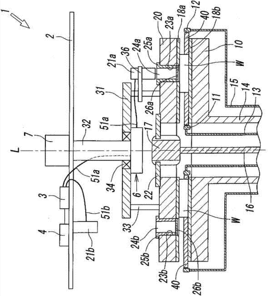
[0035] The surface polishing apparatus 1 of the present embodiment is used for polishing both surfaces of a plate-shaped workpiece W having light transmission (transparency) such as a silicon wafer, a sapphire wafer, a ceramic wafer, a crystal wafer, a glass substrate, and the like. Grinding is performed, which has: a lower fixed plate 10 rotatably supported on the machine body 2; an upper fixed plate 20 freely lifted and rotatably supported on the machine body 2; and a workpiece ground by the upper fixed plate 20 and the lower fixed plate 10 W's star wheel 40. On the lower surface of the last fixed disk 20 and the upper surface of the lower fixed disk 10, grinding pads 18a, 18b are pasted, but it is also possible to replace the grinding pads 18a, 18b for the structure of pasting abrasive grains, or the surface of the fixed disk itself is a grinding surface. structure.

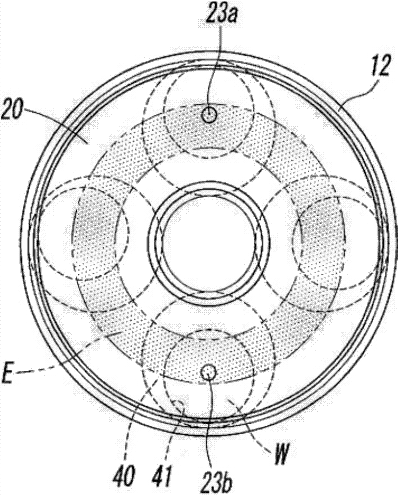
[0036] A sun gear 11 is disposed at the center of the lower fixed plate 10 , and an internal gear 12 is di...


PUM


Abstract

The present invention provides a plane polisher capable of reliably measuring both the workpiece thickness and the starwheel thickness by a laser in order to polish the gap management method based on the thickness difference between the workpiece and the starring, get measured data on the thickness of the workpiece to improve the grinding accuracy. The plane polisher (1) grinds both surfaces of the workpiece (W) while keeping the workpiece (W) on the star wheel (40), and the star wheel is disposed between the upper platen (20) and the lower platen , at least a part of which is formed of a light-transmissive material, and the plane polisher includes a first thickness measuring instrument (21a) attached to the upper platen (20) and measuring the thickness of the workpiece (W). A second thickness gauge (21b) for measuring the thickness of the star wheel (40) at a position affected by the rotation of the lower plate (20) and the lower plate (10).

Description

technical field [0001] The present invention relates to a plane lapping device for grinding a plate-shaped workpiece such as a semiconductor wafer or a glass substrate, the plate-shaped workpiece being held on a planet wheel at least partially formed of a material having light transmission, and more particularly, to measuring the workpiece and the planetary wheel. The thickness of the star wheel is a flat grinding device for grinding. Background technique [0002] For the surface grinding device, in the case of grinding both sides of the workpiece held on the planetary wheel, the thickness of the workpiece and the thickness of the planetary wheel are measured, and the difference between the thickness of the workpiece and the thickness of the planetary wheel (gap; Grinding is terminated at the time point when the interval) reaches a predetermined value, whereby a workpiece with high flatness can be obtained. [0003] In the case of performing the grinding of the so-called in...

Claims


Application Information

Patent Timeline
Patent Type & Authority Applications(China)
IPC IPC(8): B24B37/08B24B37/28B24B37/34B24B49/12
CPCB24B37/08B24B37/28B24B37/34B24B49/12B24B7/228B24B7/242B24B37/04B24B49/04B24B57/02H01L21/30625
Inventor 井上裕介吉原秀明
Owner SPEEDFAM CO LTD
Why Eureka
Try Eureka