Eureka AIR delivers breakthrough ideas for toughest innovation challenges, trusted by R&D personnel around the world.

Small-sized multi-frequency broadband deformation sleeve antenna used for mobile communication

A sleeve antenna and sleeve technology are used in antennas, antenna supports/installation devices, and devices that enable antennas to work in different frequency bands at the same time, which can solve the problem of difficulty in taking into account matching characteristics and frequency bandwidth at the same time, and the complexity of the sleeve antenna structure. , antenna operating bandwidth constraints, etc., to ensure the radiation characteristics of the antenna, facilitate processing, and simplify the structure.

Pending Publication Date: 2017-10-27
张颖松
View PDF5 Cites 3 Cited by
  • Summary
  • Abstract
  • Description
  • Claims
  • Application Information

AI Technical Summary

Problems solved by technology

However, due to the complex structure and many parameters of the sleeve, it is difficult to take into account both good matching characteristics and frequency bandwidth
Moreover, in the process of actually making the antenna, the structural size of the antenna needs to be limited by the processing conditions, which restricts the working bandwidth of the antenna to a certain extent.
[0004] Based on the shortcomings of existing sleeve antennas such as complex structure, difficult parameter adjustment, and limited processing, this invention proposes a deformed sleeve antenna structure

Method used


Image

  • Small-sized multi-frequency broadband deformation sleeve antenna used for mobile communication
  • Small-sized multi-frequency broadband deformation sleeve antenna used for mobile communication
  • Small-sized multi-frequency broadband deformation sleeve antenna used for mobile communication

Examples


no. 1 example

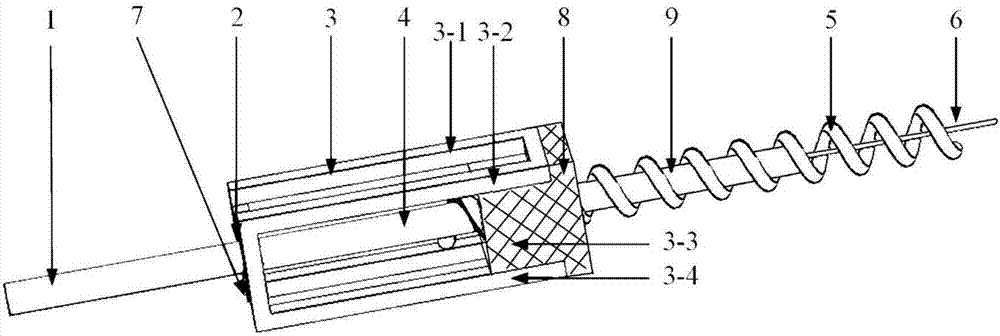
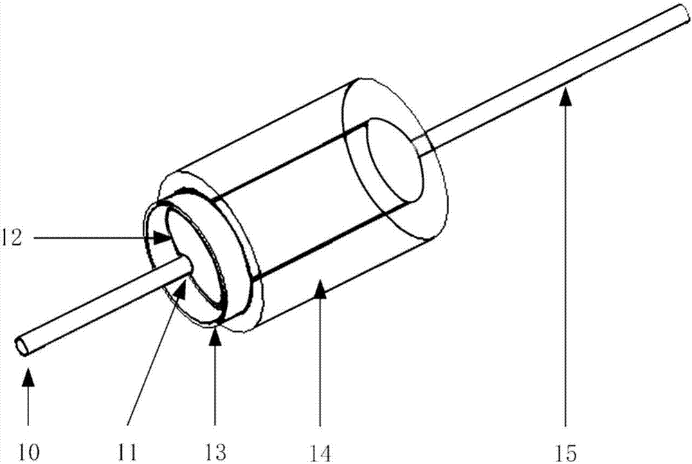
[0044] figure 1 It is a structural schematic diagram of a 4-column deformed sleeve antenna according to the present invention. The antenna includes a bottom-loaded conductor column 1, a conductive base plate 7, and an internal conductor column 4 of the antenna. The deformed sleeve antenna of the 4 columns adopts a deformed sleeve conductor column array 3 evenly arranged on the outer edge of the rectangular conductive base plate 7 to replace the traditional sleeve. The sleeve structure of the tube antenna (the structure can refer to image 3 14 and 13 in the traditional sleeve antenna structure shown);

[0045] The deformed sleeve antenna consists of a conductor post passing through the conductive base plate 7 to form the bottom-loaded conductor post 1 and the antenna inner conductor post 4: the antenna inner conductor post can be regarded as the bottom The extension of the loading conductor column, the two are integrated, the part where the conductor column is connected to t...

no. 2 example

[0054] In the antenna structure provided by the present invention, according to the requirements on the radiation characteristics of the antenna, especially, according to the different requirements of the voltage standing wave ratio (VSWR) of the antenna, a corresponding number of sleeve conductor posts can be selected. The relationship between the voltage standing wave ratio and the number of sleeve conductor columns can be referred to Figure 4 .

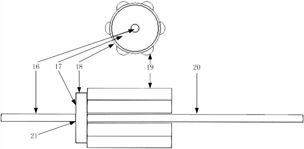
[0055] Therefore, this embodiment also provides a 6-column deformable sleeve antenna structure according to the present invention. refer to figure 2 , in this structure, the rectangular conductive bottom plate 7 in the first embodiment is transformed into a disc structure, and the six sleeve conductor columns are evenly distributed on the outer edge of the disc structure. No matter how the shape of the sleeve changes, as long as the capacitance value similar to that of the prototype sleeve structure can be obtained, the corresp...


PUM


Abstract

Disclose is a small-sized multi-frequency-band deformation sleeve antenna. The sleeve structure of the existing sleeve antenna is simplified into multiple column bodies uniformly arranged on a bottom plate; matching of antenna input impedance is realized by loading metal columns at the bottom; by virtue of such design, the same radiation characteristic as the conventional sleeve antenna is maintained while the processing difficulty of the antenna is greatly lowered; and in addition, the deformation sleeve antenna is also additionally provided with a spiral conductor structure, and corresponding electrical dimensions of the working frequency band of the antenna are provided by the spiral structure, so that the overall physical length of the deformation sleeve antenna is shortened. The invention further provides a high-frequency radiation structure which can be coupled with the deformation sleeve structure; by matching with the deformation sleeve structure, the radiation bandwidth of the antenna can be expanded effectively; and the deformation sleeve antenna provided by the invention is symmetrical in structure, simple and concise, convenient for product processing and realization, and convenient to install, so that the mechanical strength of the antenna body can be effectively improved.

Description

technical field [0001] The invention relates to the field of wireless communication hardware design, in particular to a multi-frequency broadband sleeve antenna. Background technique [0002] With the rapid development of wireless communication systems, the original traditional narrowband antennas can no longer meet the needs of continuously developing wireless communication systems. At the same time, in order to minimize the interference between antennas, it is necessary to reduce the number of antennas as much as possible. Therefore, in use, multiple communication stations usually need to share fewer antennas or even share the same antenna. This also requires that the antennas developed now can cover as many frequency bands as possible while ensuring performance requirements such as high communication efficiency, good matching, low loss, and small size. Considering the research status of the existing antennas and various requirements for antennas in modern wireless commu...

Claims


Application Information

Patent Timeline
Patent Type & Authority Applications(China)
IPC IPC(8): H01Q1/36H01Q1/14H01Q5/307
CPCH01Q1/14H01Q1/36H01Q5/307
Inventor 张颖松孙鲁兵蔡洋曹玉凡
Owner 张颖松
Why Eureka
Eureka Blog
Learn More