Position sensorless control method for permanent magnet synchronous motor based on low frequency voltage injection method

A permanent magnet synchronous motor, low-frequency voltage technology, applied in the direction of motor generator control, electronic commutation motor control, motor control, etc., can solve the problems of high-frequency noise pollution, reduce noise pollution, improve practicability, and relieve ear-piercing noise effect

Active Publication Date: 2019-11-15
HARBIN INST OF TECH
View PDF3 Cites 0 Cited by
  • Summary
  • Abstract
  • Description
  • Claims
  • Application Information

AI Technical Summary

Problems solved by technology

[0004] The purpose of the present invention is to solve the problem of high-frequency noise pollution caused by the traditional high-frequency signal injection method used at zero and low speed in the position sensorless control of the built-in permanent magnet synchronous motor, and propose a method based on the low-frequency voltage injection method. Control method of permanent magnet synchronous motor without position sensor

Method used


Image

  • Position sensorless control method for permanent magnet synchronous motor based on low frequency voltage injection method
  • Position sensorless control method for permanent magnet synchronous motor based on low frequency voltage injection method
  • Position sensorless control method for permanent magnet synchronous motor based on low frequency voltage injection method

Examples


specific Embodiment approach 1

[0024] Embodiment 1: The control method of the permanent magnet synchronous motor without position sensor based on the low-frequency voltage injection method includes the following steps:

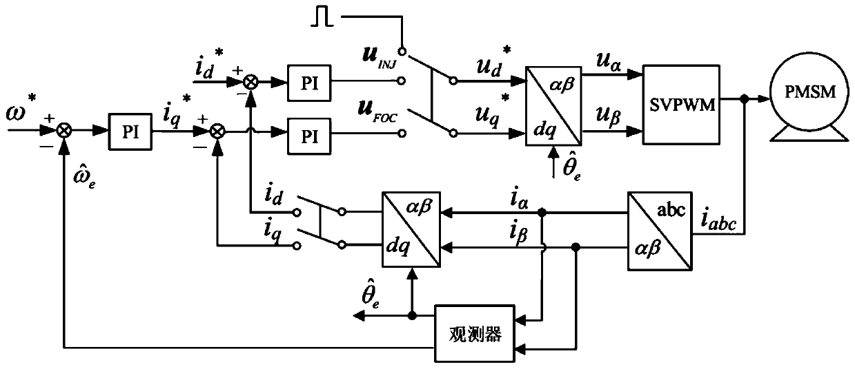
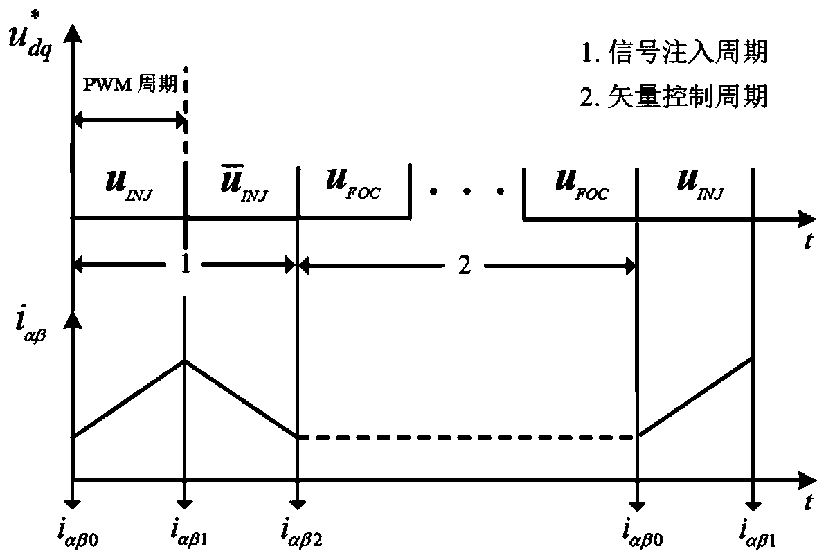
[0025] Step 1: During the operation of the permanent magnet synchronous motor, inject low-frequency pulse voltage into the dq shafting of the permanent magnet synchronous motor through the control of the microprocessor; in order to avoid the interference of the filter on the low-frequency voltage, the control sequence of the motor is divided into injection Period and control period are beneficial to the injection and extraction of low-frequency pulse voltage; the dq axis system refers to the rotating coordinate system of the motor. When the low-frequency pulse voltage is injected, it is the injection period, and when the motor is controlled, it is the control period; the dq axis system includes d-axis and q axis, the d-axis points to the N-pole direction of the rotor magnetic field, and the ...

specific Embodiment approach 2

[0029]Specific embodiment 2: The difference between this embodiment and specific embodiment 1 is that in the step 1, during the operation of the permanent magnet synchronous motor, a low-frequency pulse voltage is injected into the dq shafting of the permanent magnet synchronous motor through the control of the microprocessor Specifically:

[0030] Inject a low-frequency pulse voltage into the dq axis of the vector control system:

[0031]

[0032] where u dqi is the low-frequency pulse voltage injected into the dq axis system, k is the control sequence, and k=1,2,3,...,V i is the magnitude of the injected voltage;

[0033] A method is employed in which the injection period and the control period are separated from each other. Such as figure 1 shown. The way of pulse voltage injection is equivalent to a switch, which is located at the output position of the current loop. When performing motor control, the given voltage under the dq axis system is the output voltage of...

specific Embodiment approach 3

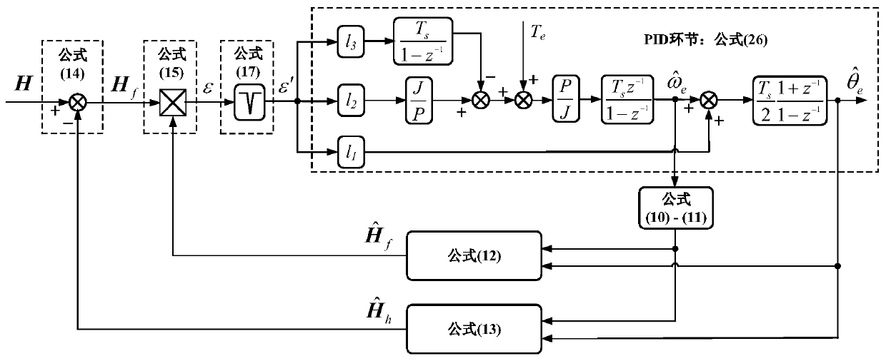
[0037] Embodiment 3: The difference between this embodiment and Embodiment 1 or 2 is that in the second step, the pulse current information is extracted from the αβ shafting of the permanent magnet synchronous motor, and the quadrature signal of the rotor position is obtained through current differential calculation. The specific process is:

[0038] The dq shaft system equation of the permanent magnet synchronous motor is:

[0039]

[0040] where u d and u q are the stator voltages of d-axis and q-axis respectively, where i d and i q are the stator currents of d-axis and q-axis respectively, R s is the stator resistance, L d and L q are the stator inductances of d-axis and q-axis respectively, ω e is the electrical speed of the motor, ψ f is the rotor flux linkage;

[0041] Transform the formula (2) into the αβ axis through the coordinate transformation. Assuming that the injected voltage amplitude is large enough, the voltage drop on the resistor and the influenc...


PUM


Abstract

The invention discloses a low-frequency voltage injection method-based position-sensorless control method for a permanent magnet synchronous motor, relates to a position-sensorless control method for the permanent magnet synchronous motor and aims to solve the problem of high-frequency noise pollution caused by a conventional high-frequency signal injection method at zero and low speeds during position-sensorless control over a built-in permanent magnet synchronous motor. The method comprises the following steps: I: in an operation process of the permanent magnet synchronous motor, injecting low-frequency pulse voltage into a dq shaft system of the permanent magnet synchronous motor through micro processor control, and dividing a control sequence of the motor into an injection period and a control period; II: calculating a position orthogonal signal of a rotor through current differentiation according to pulse current information extracted from an alpha-beta shaft system of the permanent magnet synchronous motor; and III: designing a vector tracker based on spatial Fourier transformation, thus obtaining a position and a rotating speed of the rotor for closed-loop control over the rotating speed and the current of the motor to realize position-sensorless control. The low-frequency voltage injection method-based position-sensorless control method for the permanent magnet synchronous motor is applied to the technical field of motor control.

Description

technical field [0001] The invention relates to the technical field of motor control, in particular to a control method for a built-in permanent magnet synchronous motor with low noise and no position sensor. Background technique [0002] Permanent magnet synchronous motors are widely used in various fields because of their high power density, high torque density and good dynamic performance. Traditional vector control technology requires motor rotor position information for decoupling control, but the installation of position sensors not only increases the cost, but also reduces the reliability of the system, so position sensorless technology has become one of the main research directions in the field of motor control. [0003] The position sensorless technology is mainly divided into the high-frequency signal injection method used at zero and low speeds and the model method used at medium and high speeds. Because the model method is greatly affected by noise when the spee...

Claims


Application Information

Patent Timeline
Patent Type & Authority Patents(China)
IPC IPC(8): H02P21/04H02P21/18
CPCH02P21/04H02P21/18H02P2203/03
Inventor 王高林肖殿勋张国强赵楠楠于泳徐殿国
Owner HARBIN INST OF TECH
Why Eureka
Try Eureka