Waste heat power generation system and method with high-fly-ash gas as heat source

A waste heat power generation and heat source technology, which is applied to machines/engines, steam engine devices, mechanical equipment, etc., can solve the problems of lower flue gas grade, high water consumption, and high moisture content of flue gas, and achieves reduction in size and overall water consumption. high effect

Active Publication Date: 2017-11-03
NANJING UNIV OF AERONAUTICS & ASTRONAUTICS
View PDF3 Cites 0 Cited by
  • Summary
  • Abstract
  • Description
  • Claims
  • Application Information

AI Technical Summary

Problems solved by technology

Although this method has a good dust removal effect and does not have high requirements on the particle size of the dust particles, the grade of the flue gas is significantly reduced, and the moisture content of the purified flue gas is high, and the overall water consumption is relatively high.

Method used


Image

  • Waste heat power generation system and method with high-fly-ash gas as heat source

Examples


Embodiment Construction

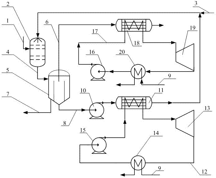
[0035] Refer to the attached figure 1 The operation process of the waste heat power generation system with the high-flying ash flue gas as the heat source is described.

[0036] First of all, the heat source of high-flying ash flue gas 1 first enters the flue gas inlet of the heat and mass transfer tank 2, mixes with the circulating fluid entering from the spray liquid inlet, and a sufficient heat and mass exchange occurs in the heat and mass transfer tank 2, Change into mixed product 4 and discharge from heat and mass co-transfer tank 2 outlet;

[0037] Then, the mixed product 4 enters the cyclone separator 5 and is divided into three paths:

[0038] The first road is the sludge 7 after sedimentation, which is directly discharged to the environment after being deposited to a certain thickness;

[0039] The second way is that the clean flue gas 6 passes through the hot side of the flue gas heat source evaporator 18, releases sensible heat and latent heat to the second organi...


PUM


Abstract

The invention provides a waste heat power generation system and method with high-fly-ash gas as a heat source and belongs to the field of energy saving and emission reduction. According to the system, thermal mass simultaneous conduction is achieved mainly through a thermal mass simultaneous conduction tank (2) in a direct contact mode, ash in high-fly-ash smoke (1) is transferred to low-temperature clear liquor (8), and purposes of ash removing and waste heat recycling are achieved. Then by means of waste heat recycling organic Rankine cycle connected in parallel, recycling and power generation are conducted on waste heat in high-temperature smoke (6) with ash removed and the clear liquor (8). In addition, due to the fact that the system conducts cyclic recovery on the clear liquor (8), the absolute consumption of water is not high. The system is suitable for fly ash collection and waste heat recycling of high fly ash and high-temperature smoke generated by industrial kilns.

Description

technical field [0001] The invention relates to a waste heat power generation system and method using high-fly ash gas as a heat source, and belongs to the field of energy saving. technical background [0002] The exhaust gas temperature of industrial kilns is relatively high, which is a high-grade medium-temperature waste heat source. However, due to the large amount of fly ash in the flue gas of industrial kilns, the heat transfer coefficient of the flue gas itself is not high, and the deposition of fly ash is easy to block the heat transfer channel, or increase the thermal resistance of heat transfer dirt, so the direct use of heat exchangers through the indirect It is difficult to effectively recover the waste heat in the high fly ash flue gas by means of heat recovery. Therefore, before the waste heat recovery of flue gas containing fly ash, the fly ash contained in it needs to be effectively separated, and then the waste heat of the flue gas should be recycled. [00...

Claims


Application Information

Patent Timeline
Patent Type & Authority Applications(China)
IPC IPC(8): F01K27/00F01K25/08F01K23/18F01K13/00F01D15/10
CPCF01D15/10F01K13/006F01K23/18F01K25/08F01K27/00
Inventor 韩东岳晨蒲文灏何纬峰
Owner NANJING UNIV OF AERONAUTICS & ASTRONAUTICS
Why Eureka
Try Eureka