
Turf sodding device achieving continuous sodding

A turf and grass laying technology, which is applied in the directions of plant cultivation, lawn growth, and botanical equipment and methods, can solve the problems of single function, single function of the laying machine, poor lawn laying efficiency, etc., and achieve the effect of improving the flatness.

Inactive Publication Date: 2017-11-07
重庆雷步特科技有限责任公司
View PDF5 Cites 3 Cited by
  • Summary
  • Abstract
  • Description
  • Claims
  • Application Information

AI Technical Summary

Problems solved by technology

[0004] The technical problem to be solved by the present invention is that the existing laying machine has a single function and poor lawn planting efficiency. The problem

Method used


Image

  • Turf sodding device achieving continuous sodding
  • Turf sodding device achieving continuous sodding

Examples


Embodiment 1

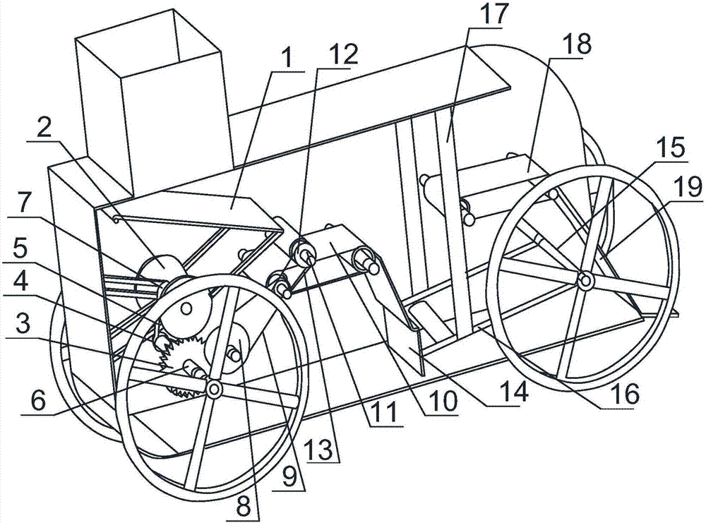
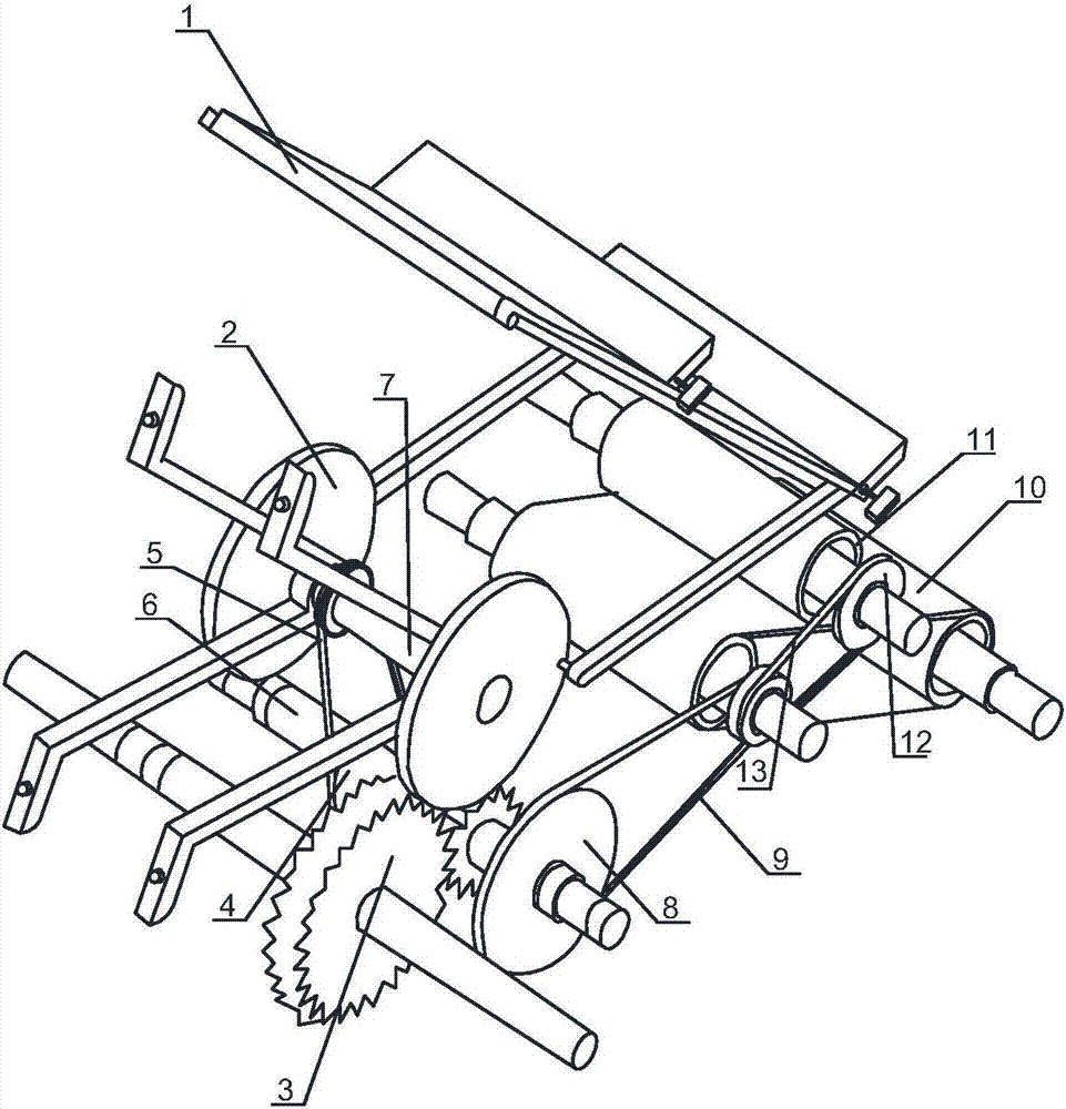
[0025] Such as figure 1 , figure 2As shown, the turf planting device capable of continuous planting of the present invention comprises a vehicle body, an intermittent feeding mechanism installed at the front of the vehicle body and an unfolding mechanism connected to the intermittent feeding mechanism, and a Grass-laying structure, intermittent feeding mechanism, unfolding mechanism, and grass-laying structure are all located inside the vehicle body. The intermittent feeding mechanism includes a slant plate 1 with one end inclined downward, crank set 2, meshing gear set 3, A-type pulley I4, A-type belt I5, the lower surface of the lower end of the swash plate 1 is hinged with the connecting rod of the crank set 2, a gear in the meshing gear set 3 is connected with the A-type pulley I4 through the rotating shaft 6, and the A-type pulley I4 passes through the A-type belt I5 It is connected with the crankshaft 7 of the crankset 2; the unfolding mechanism includes A-type pulley ...

Embodiment 2

[0030] Based on Embodiment 1, the discharge plate 19 includes a long plate connected to one end of the conveyor belt 18, the other end of the long plate is inclined to the rear and downward of the conveyor belt 18, and the lower end of the long plate is connected to a horizontal plate. Form an L-shaped discharge plate with the horizontal plate. The length of the horizontal plate in the L-shaped discharge plate is very short, the turf will not stay on the horizontal plate, and the horizontal plate can play a buffer role for the turf, so that the turf can be laid on the ground slowly, avoiding the turf falling too fast and colliding with the car body Poor speed fit for laying turf quickly and with high quality.

Embodiment 3

[0032] Based on the above embodiment, the soft board 14 includes a plurality of rectangular boards arranged in parallel, and adjacent rectangular boards are connected by springs.

[0033] The spring connection is beneficial to fine-tuning the length of the soft board according to the installation position of the conveyor belt during the rising process, which is convenient to use, and the soft board is flexible.


PUM


Abstract

The invention discloses a turf sodding device achieving continuous sodding. The device comprises a vehicle body, an intermittent feeding mechanism, an unfolding mechanism and a sodding structure; the intermittent feeding mechanism, the unfolding mechanism and the sodding structure are all located in the vehicle body, and the intermittent feeding mechanism comprises an inclined plate, a crank set, a meshed gear set, an A-type belt pulley I and an A-type belt I; the unfolding mechanism comprises an A-type belt pulley II, an A-type belt II, a conveyor belt, a hollow roller, an A-type belt pulley III and an A-type belt III; the sodding structure comprises a support shaft connected with a soft plate, at least two connecting rods are connected between the support shaft and the soft plate, a telescopic rod adjusting the height of the soft plate is vertically connected to the portion above the connecting rods, the sodding structure further comprises a conveying belt with the conveying direction same as that of the conveyor belt, the conveying belt is connected with the conveyor belt through the soft plate, and a discharge plate used for laying turf outwards is arranged at the tail of the vehicle body. Accordingly, the problem that an existing turf sodding machine is poor in sodding efficiency is solved.

Description

technical field [0001] The invention relates to a turf laying device, in particular to a turf laying device capable of continuous planting. Background technique [0002] Turf, more common in gardens, parks, or cut grass to a fixed length for various sports such as football, rugby, baseball, softball, tennis, golf, etc.; with a thin layer of soil shoveled down the grass, It is used to pave lawns to beautify the environment, or to lay on the surface of embankments to prevent erosion; the type of turf is 75% fine-leaf grass and 25% large-leaf grass. [0003] At present, the existing lawn paving machines are of high quality, large in size, complex in structure, difficult to operate, and take a long time. They are only suitable for laying large-scale sites, have low cost performance, and have single functions. Execution; For small-scale turf paving, it is generally based on manual paving, which consumes manpower and has low efficiency; . Contents of the invention [0004] Th...

Claims


Application Information

Patent Timeline
Patent Type & Authority Applications(China)
IPC IPC(8): A01G1/00
CPCA01G20/10
Inventor 伍国果金容谢文烽王勇
Owner 重庆雷步特科技有限责任公司
Learn More