Ozone full-utilization type sludge reduction reaction system and sludge treatment method

A reaction system and sludge treatment technology, applied in the field of ozone full utilization sludge reduction reaction system and sludge treatment, can solve the problems that are not conducive to large-scale popularization and application, slow sludge oxidation reaction, low ozone utilization efficiency, etc. , to achieve the effect of simple structure, small footprint and remarkable effect

Pending Publication Date: 2017-11-07
江苏浦坤纳米科技有限公司
View PDF7 Cites 3 Cited by
  • Summary
  • Abstract
  • Description
  • Claims
  • Application Information

AI Technical Summary

Problems solved by technology

[0005] However, because ozone exists in the form of gas, there are gas-solid, solid-liquid and other mass transfer problems in the oxidation process of sludge, which makes the utilization efficiency of ozone low, so that it is subject to certain restrictions in the application of sludge treatment process. limit
For example, in the patent ZL 201310645801.9, an eductor is used to dissolve ozone, resulting in a very low utilization rate of ozone, not only wasting ozone, but also the sludge oxidation reaction is very slow
In addition, the equipment structure of the reaction system is complex and the investment is high, which is not conducive to large-scale application

Method used


Image

  • Ozone full-utilization type sludge reduction reaction system and sludge treatment method

Examples


Embodiment 1

[0036] In this embodiment, sludge reduction is carried out for the low dosage of ozone in the reaction tank 1 .

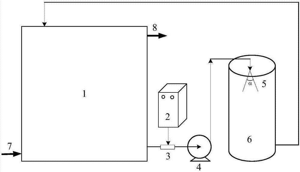
[0037] The inlet of the ejector 3 is installed on the outlet of the reaction tank 1, and the air inlet of the ejector 3 is connected with the outlet pipe of the 30 g / h ozone generator 2 at the same time. Install the booster pump 4 so that its inlet is connected to the outlet of the ejector 3 . A large downward horn-shaped nozzle 5 is installed on the inside of the mixing tank 6, the angle of the horn is 10 degrees, and the height is 1 / 10 of the height of the mixing tank 6, and the outlet of the booster pump 4 is connected to the inlet of the nozzle 5. A sludge outlet is installed at the bottom of the mixing tank 6 and connected to the reaction tank 1 . The inlet of the sludge to be treated and the sludge outlet 8 after the reduction reaction is completed are installed on the reaction tank 1 .

[0038]The 30L reaction tank 1 was filled with sludge with an MLSS con...

Embodiment 2

[0042] In this embodiment, sludge reduction is performed by increasing the ozone dosage in the reaction tank 1 .

[0043] The inlet of the ejector 3 is installed on the outlet of the reaction tank 1, and the air inlet of the ejector 3 is connected with the outlet pipe of the 25.5g / h ozone generator 2 at the same time. Install the booster pump 4 so that its inlet is connected to the outlet of the ejector 3 . A large mouth downward horn-shaped nozzle 5 is installed on the inside of the mixing tank 6, the angle of the horn is 30 degrees, and the height is 1 / 5 of the height of the mixing tank 6, and the outlet of the booster pump 4 is connected to the inlet of the nozzle 5. A sludge outlet is installed at the bottom of the mixing tank 6 and connected to the reaction tank 1 . The inlet of the sludge to be treated and the sludge outlet 8 after the reduction reaction is completed are installed on the reaction tank 1 .

[0044] The 40L reaction tank 1 was filled with sludge with an ...

Embodiment 3

[0048] In this embodiment, sludge reduction is performed by increasing the ozone dosage in the reaction tank 1 .

[0049] The inlet of the ejector 3 is installed on the outlet of the reaction tank 1, and the air inlet of the ejector 3 is connected with the outlet pipe of the 30 g / h ozone generator 2 at the same time. Install the booster pump 4 so that its inlet is connected to the outlet of the ejector 3 . A large downward horn-shaped nozzle 5 is installed on the inside of the mixing tank 6, the angle of the horn is 20 degrees, and the height is 1 / 8 of the height of the mixing tank 6, and the outlet of the booster pump 4 is connected to the inlet of the nozzle 5. A sludge outlet is installed at the bottom of the mixing tank 6 and connected to the reaction tank 1 . The inlet of the sludge to be treated and the sludge outlet 8 after the reduction reaction is completed are installed on the reaction tank 1 .

[0050] The 40L reaction tank 1 was filled with sludge with an MLSS co...


PUM


Abstract

The invention relates to an ozone full-utilization type sludge reduction reaction system. The sludge reduction reaction system comprises a reaction slot, a jet device, an ozone generator and a spray head, wherein the jet device is connected with the reaction slot, the ozone generator is used for supplying ozone into the jet device, and the spray head is communicated with the jet device; and the jet device is connected with the spray head through a booster pump, a mixing tank for receiving jetted matters is arranged below the spray head, and a sludge outlet of the mixing tank is communicated with the reaction slot, so as to form a circulation channel. The system has the beneficial effects that the structure is simple, the occupied area is small, the investment is saved, the operation is simple, the reaction efficiency is high, ozone can be completely utilized, and an ozone decomposer is not used; the sludge reduction effect is remarkable, and the amount of sludge can be reduced by 50%-90% or above; and the system is well compatible with an existing sludge process and can be applied to sludge reduction of sewage treatment plants in large scale.

Description

technical field [0001] The invention relates to a sludge treatment system and a treatment method, in particular to a sludge reduction reaction system and a sludge treatment method for full utilization of ozone. Background technique [0002] As the most widely used biological water treatment technology at home and abroad, one of the main problems of activated sludge process is that it produces a large amount of excess sludge. The investment and operation cost of the excess sludge treatment plant accounts for about 25%-65% of the investment and operation cost of the entire sewage treatment plant. The huge sludge disposal cost has become a serious problem faced by sewage biological treatment technology. At present, sewage treatment plants generally use landfill and composting methods to treat sludge. However, these two methods will cause the heavy metal content in the soil to exceed the standard, which seriously threatens the human living environment. Therefore, how to take re...

Claims


Application Information

Patent Timeline
Patent Type & Authority Applications(China)
IPC IPC(8): C02F11/06
CPCC02F11/06
Inventor 杨庆峰陈崇友董康正
Owner 江苏浦坤纳米科技有限公司
Why Eureka
Try Eureka