Low power consumption power capacitor fast discharge device

A technology of power capacitors and discharge devices, which is applied in the direction of output power conversion devices, circuit devices, electrical components, etc., can solve problems such as inability to track compensation in real time, long discharge time, overcompensation, etc., to avoid insulation damage and clutter Effects of interference, ensuring safe operation, and slowing down the waveform

Inactive Publication Date: 2017-11-07
王联喜 +2
View PDF3 Cites 1 Cited by
  • Summary
  • Abstract
  • Description
  • Claims
  • Application Information

AI Technical Summary

Problems solved by technology

Therefore, the compromise method of many capacitor manufacturers is to use a 200K discharge resistor, so that the discharge time of a small-capacity capacitor is acceptable, but when the capacitor capacity is large, the discharge time is still too long; according to the measurement, the capacitor of the existing compensation device The average action delay of the group is 40 seconds. When the react

Method used


Image

  • Low power consumption power capacitor fast discharge device
  • Low power consumption power capacitor fast discharge device
  • Low power consumption power capacitor fast discharge device

Examples


Embodiment Construction

[0030] In order to make the object, technical solution and advantages of the present invention clearer, the present invention will be further described in detail below in conjunction with the accompanying drawings and specific embodiments. It should be understood that the specific embodiments described here are only used to explain the present invention, and are not intended to limit the present invention.

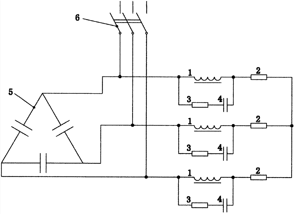
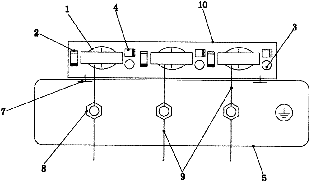
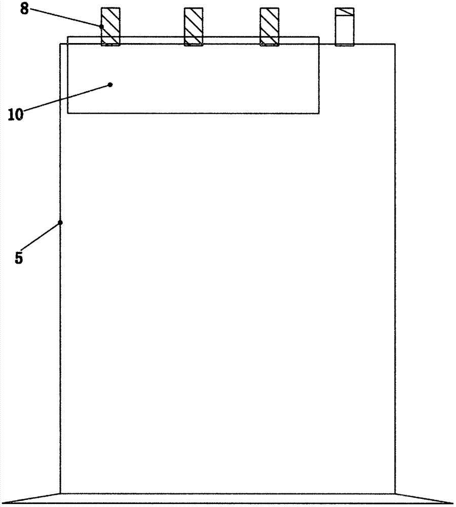
[0031] see figure 2 , image 3 , the specific embodiment adopts the following technical solutions: it includes a choke coil 1, a discharge resistor 2, an absorbing resistor 3, an absorbing capacitor 4, a three-phase power capacitor bank 5, a switching switch 6, a discharge device hook 7, and capacitor bank wiring Pile 8, connecting wire 9 and discharge device outer box 10, RC resistance-capacitance overvoltage absorber composed of choke coil 1, absorbing resistor 3, and absorbing capacitor 4 are connected in parallel and then connected in series with discharging resistor...


PUM

PropertyMeasurementUnit
Sizeaaaaaaaaaa
Dc resistanceaaaaaaaaaa
Coil turnsaaaaaaaaaa

Abstract

The invention discloses a low power consumption power capacitor fast discharge device, and relates to the technical field of power grid alternating current power reactive compensation. The device comprises circuit units. Each circuit unit comprises a choke coil, a discharge resistor and an RC resistance-capacitance overvoltage absorber. Each choke coil is connected in parallel with a RC resistance-capacitance overvoltage absorber, and then is connected in series with a discharge resistor. Each RC resistance-capacitance overvoltage absorber comprises an absorption capacitor and an absorption resistor. Each absorption capacitor is connected in series with an absorption resistor, and then is connected in parallel with both ends of a choke coil. Three sets of circuit units are star-connected with A/B/C ports of a three-phase capacitor, wherein the neutral point is impending. Each absorption capacitor uses a ceramic capacitor with the rated voltage of 630V, and the capacity is 0.1uF. Each absorption resistor uses a carbon resistor with the powder of 1W. Each choke coil uses an EI type single winding transformer coil, and the input rated voltage is AC 250V. The device provided by the invention has the advantages of small running power consumption, stable operation without maintenance, low cost and short discharge time, and each set is less than 15 yuan.

Description

technical field [0001] The invention relates to the technical field of reactive power compensation for grid AC power, in particular to a power capacitor with a voltage level below 1000V, which is suitable for low-power consumption in reactive power compensation equipment such as public transformers, private line customers, substations, and power stations. Capacitor quick discharge device. Background technique [0002] High and low voltage AC power capacitors are not allowed to be switched on with residual charge; otherwise, at the moment of switching on, the input potential of the power grid and the residual potential of the capacitor may be reversed, and a large voltage will be generated when the potential difference is large. Current shock, in addition to causing switch tripping, overcurrent damage to the knife switch, and capacitor explosion, sharp pulses will also interfere with the normal operation of control equipment, and even cause accidents. Therefore, "DL / T1417-20...

Claims


Application Information

Patent Timeline
IPC IPC(8): H02J3/18H02M1/32
CPCH02J3/1864H02M1/32H02M1/322Y02E40/30
Inventor 王联喜余卫华程冬秀
Owner 王联喜
Why Eureka
Try Eureka