Three-phase four-wire zero-voltage switch rectifier circuit with balancing bridge arm, and modulation method for three-phase four-wire zero-voltage switch rectifier circuit

A technology of zero-voltage switching and rectifier circuits, applied in the field of rectifiers, can solve the problems of reducing circuit efficiency, large switching losses of converter devices, large filters, etc., and achieve high circuit efficiency, small switching losses, and improved power density.

Active Publication Date: 2017-11-10
ZHEJIANG UNIV
View PDF3 Cites 13 Cited by
  • Summary
  • Abstract
  • Description
  • Claims
  • Application Information

AI Technical Summary

Problems solved by technology

The circuit works in a hard switching state, there is a diode reverse recovery phenomenon, and the switching loss of the converter device is large, which limits the improvement of the operating frequency, resulting in the need to use a larger filter and reducing the circuit efficiency

Method used


Image

  • Three-phase four-wire zero-voltage switch rectifier circuit with balancing bridge arm, and modulation method for three-phase four-wire zero-voltage switch rectifier circuit
  • Three-phase four-wire zero-voltage switch rectifier circuit with balancing bridge arm, and modulation method for three-phase four-wire zero-voltage switch rectifier circuit
  • Three-phase four-wire zero-voltage switch rectifier circuit with balancing bridge arm, and modulation method for three-phase four-wire zero-voltage switch rectifier circuit

Examples


Embodiment Construction

[0022] The present invention will be described in detail below in conjunction with the accompanying drawings.

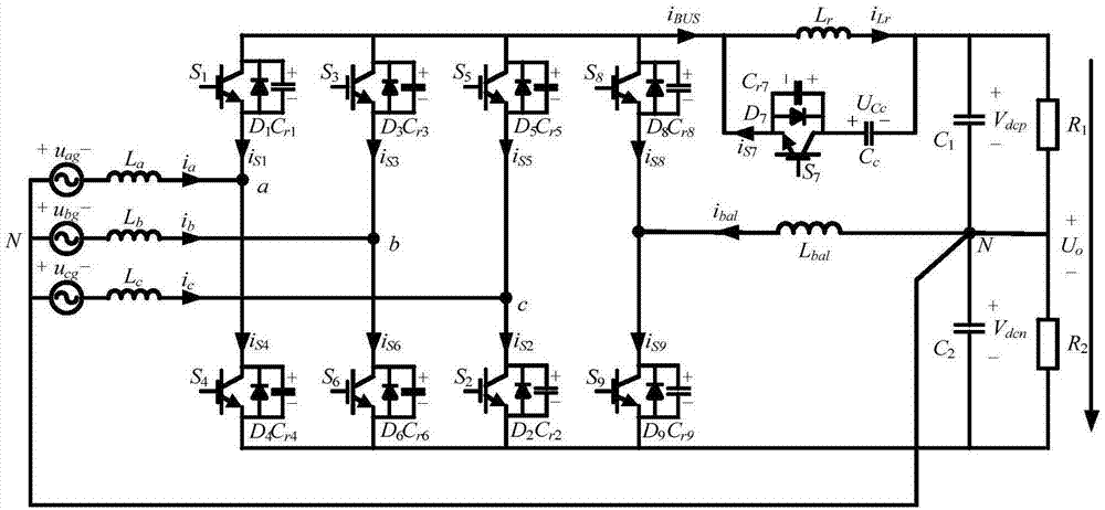
[0023] refer to figure 1 , a three-phase four-wire zero-voltage switching rectifier circuit with a balanced bridge arm includes a DC side series load R 1 and R 2 , DC side series capacitor group C 1 and C 2 , and four groups of bridge arms; each group of bridge arms is composed of two series-connected fully-controlled switches containing anti-parallel diodes, wherein: the upper and lower switches of the first bridge arm and their anti-parallel diodes are S 1 , S 4 and D 1 、D 4 , the upper and lower switches of the second bridge arm and their anti-parallel diodes are respectively S 3 , S 6 and D 3 、D 6 , the upper and lower switches of the third bridge arm and their anti-parallel diodes are respectively S 5 , S 2 and D 5 、D 2 , the upper and lower switches of the fourth bridge arm and their anti-parallel diodes are S 8 , S 9 and D 8 、D 9 , the midpoi...


PUM


Abstract

The invention discloses a three-phase four-wire zero-voltage switch rectifier circuit with a balancing bridge arm, and a modulation method for the three-phase four-wire zero-voltage switch rectifier circuit. The circuit comprises a DC side load of the rectifier circuit, a DC side series capacitor, an AC side filter inductor, a balancing bridge arm inductor, and four groups of bridge arms which are composed of two full-control main switches with anti-parallel diodes. An auxiliary switch comprising an anti-parallel diode, and a resonant branch circuit composed of the clamping capacitor and a resonant inductor are connected between a DC side bus capacitor and a bus of the four groups of bridge arms. Two ends of the main switch and the auxiliary switch are in parallel connection with capacitors. According to the invention, the circuit achieves the synchronization of the pulse signals of the auxiliary switch and the main switch, can achieve the zero-voltage connection of all switches in each switching period, effectively inhibits the reverse recovery current of the anti-parallel diode of the main switch, is small in switching loss, is high in circuit efficiency, facilitates the improvement of the switching frequency, and improves the system power density.

Description

technical field [0001] The invention relates to the technical field of rectifiers, in particular to a three-phase four-wire zero-voltage switch rectifier circuit with a balanced bridge arm and a modulation method thereof. Background technique [0002] A traditional two-level three-phase four-wire PWM rectifier with balanced legs consists of six fully controlled main switches (S 1 ~S 6 ) composed of three-phase bridge arm, three input filter inductors (L a , L b , L c ), two DC bus capacitors (C 1 , C 2 ), the fully controlled main switch (S 8 , S 9 ) composed of the first balanced bridge arm and the balanced inductance L across the midpoint of the balanced bridge arm and the midpoint of the bus capacitance bal , connected to the neutral point of the positive and negative bus capacitors and the neutral point of the power grid. The circuit works in a hard switching state, there is a diode reverse recovery phenomenon, and the switching loss of the converter device is l...

Claims


Application Information

Patent Timeline
Patent Type & Authority Applications(China)
IPC IPC(8): H02M7/219H02M7/217
CPCH02M7/2173H02M7/219H02M1/0058Y02B70/10
Inventor 徐德鸿施科研赵安
Owner ZHEJIANG UNIV
Why Eureka
Try Eureka