Supercharge Your Innovation With Domain-Expert AI Agents!

Charging circuit and battery

A charging circuit and charging circuit technology, applied in battery circuit devices, circuit devices, current collectors, etc., can solve the problems of reduced safety and high battery core temperature, and achieve the effect of preventing excessive temperature and improving safety.

Inactive Publication Date: 2017-11-14
NANJING ZGMICRO CO LTD
View PDF3 Cites 3 Cited by
  • Summary
  • Abstract
  • Description
  • Claims
  • Application Information

AI Technical Summary

Problems solved by technology

[0005] The embodiment of the present application provides a charging circuit and a battery, which are used to solve the problem of safety degradation caused by excessive battery temperature during the charging process in the prior art

Method used


Image

  • Charging circuit and battery

Examples


Embodiment 1

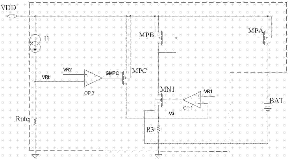
[0015] figure 1 A circuit diagram of a charging circuit according to Embodiment 1 of the present application is shown.

[0016] Such as figure 1 As shown in the circuit in the dotted line box, the charging circuit according to Embodiment 1 of the present application includes:

[0017] A charging circuit, the charging circuit includes a second PMOS transistor MPA, a third PMOS transistor MPB, a first NMOS transistor MN1, a resistor R3, and a second operational amplifier OP1;

[0018] A sensor, the sensor is located in the battery, and the distance from the battery cell BAT is less than a predetermined distance, and is used to sense the temperature of the battery cell;

[0019] A current source is used to provide current for the thermistor Rntc;

[0020] The first PMOS transistor MPC is used to shunt the charging current of the charging circuit when it is turned on;

[0021] The first operational amplifier OP2 is used to control the conduction of the first PMOS transistor wh...

Embodiment 2

[0042] Based on the same inventive concept, a battery is also provided in the embodiment of the present application.

[0043] The battery according to the second embodiment of the present application includes: a battery cell BAT, and the charging circuit according to the first embodiment of the present application.

[0044] The specific implementation of the charging circuit in the battery in the embodiment of the present application can refer to the implementation of the charging circuit in the first embodiment of the present application, and repeated descriptions will not be repeated.

[0045] Using the battery in the embodiment of this application, the temperature of the battery core is sensed by a sensor with a positive temperature coefficient or a negative temperature coefficient. When the sensor detects that the temperature of the battery core is too high, the first PMOS transistor MPC is turned on to charge the charging circuit. The current is shunted to reduce the char...


PUM


Abstract

An embodiment of the invention provides a charging circuit which includes a charging loop, a sensor, a constant current source, a field effect transistor, and a first operational amplifier OP2. The charging loop is used for charging a battery core. The sensor is disposed in a battery and used for sensing the temperature of the battery core. The distance between the sensor and the battery core is smaller than a predetermined distance. The sensor is a sensor having a negative or positive temperature coefficient. The constant current source is used for supplying a current to the sensor. The field effect transistor is used for shunting the charging current of the charging loop when switched on. The first operational amplifier OP2 is used for making the field effect transistor switched on when the temperature of the battery core sensed by the sensor exceeds a predetermined temperature Tch, wherein the predetermined temperature is a preset maximum charging temperature of the battery core. According to the scheme of the invention, the charging safety is improved by preventing the temperature of the battery core from being too high during charging.

Description

technical field [0001] The present application relates to the field of integrated circuit design, and in particular, relates to a charging circuit and a battery. Background technique [0002] For electronic devices, because faster charging saves more time, especially for portable electronic devices, users often need a fast charging function, and devices with faster charging are more popular. Therefore, in recent years, a lot of research has been conducted on various fast charging technologies. [0003] Usually, the method of increasing the charging current is used to speed up the charging speed. [0004] However, the inventors found that when the charging current is increased, the temperature of the battery core becomes another limitation. That is, when the charging current is large and the charging duration is long, the temperature of the battery cell will rise. If the temperature of the battery cell is too high, the performance of the battery may decrease, and in severe ...

Claims


Application Information

Patent Timeline
IPC IPC(8): H02J7/00
CPCH02J7/00H02J7/0091
Inventor 王钊
Owner NANJING ZGMICRO CO LTD
Features
  • R&D
  • Intellectual Property
  • Life Sciences
  • Materials
  • Tech Scout
  • Unparalleled Data Quality
  • Higher Quality Content
  • 60% Fewer Hallucinations
Learn More