fuel injection valve
A fuel injection valve and fuel technology, which is applied in fuel injection devices, charging systems, machines/engines, etc., can solve problems such as the deterioration of atomization, achieve stress suppression, compact overall structure, and suppress the deterioration of atomization
- Summary
- Abstract
- Description
- Claims
- Application Information
AI Technical Summary
Problems solved by technology
Method used
Image
Examples
Embodiment approach 1
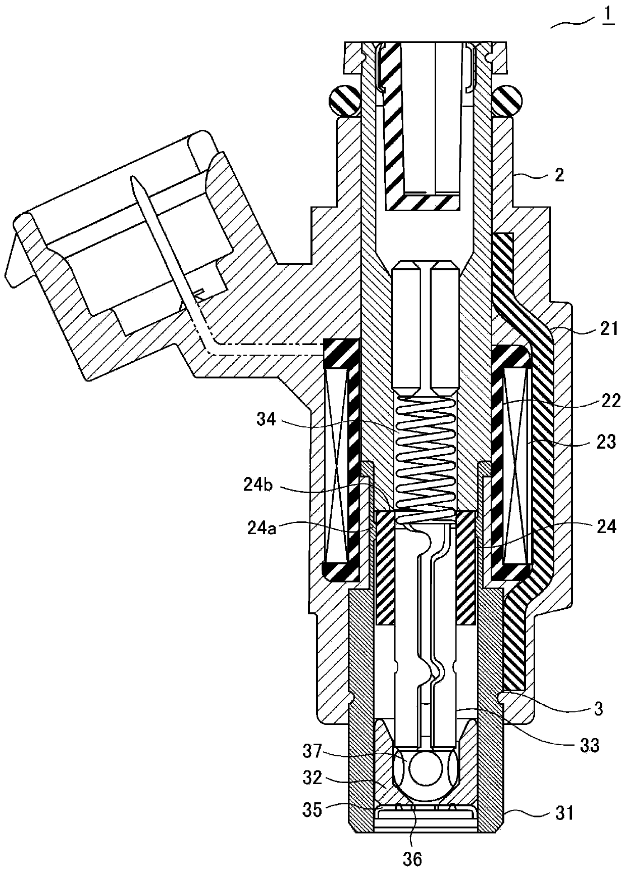
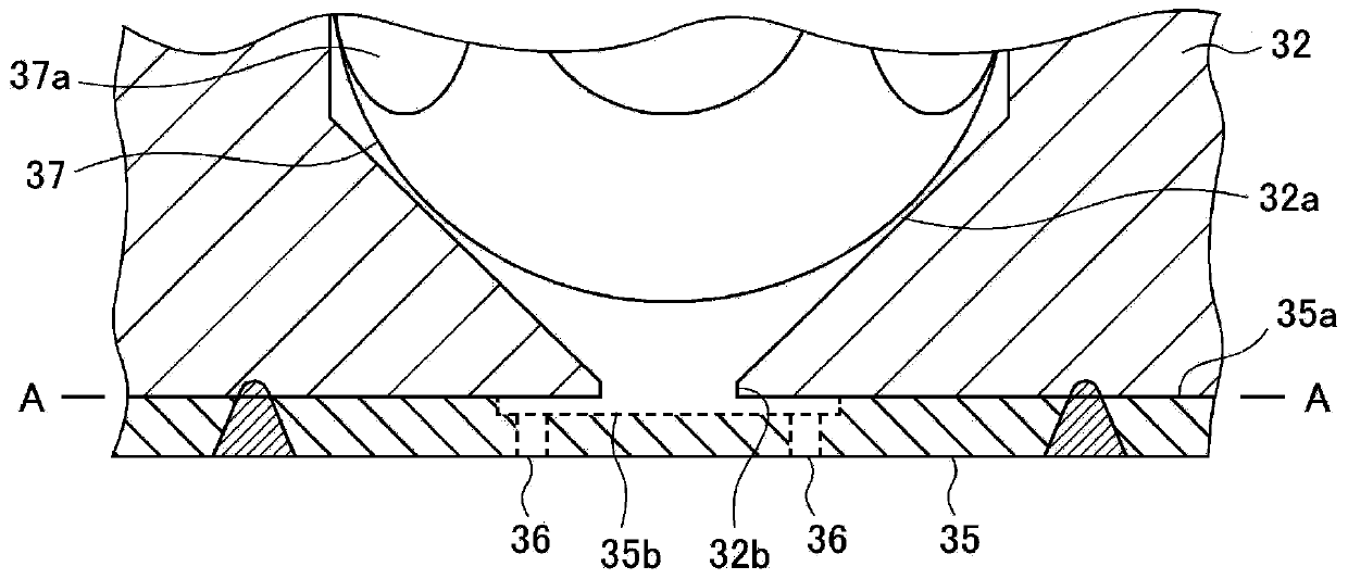
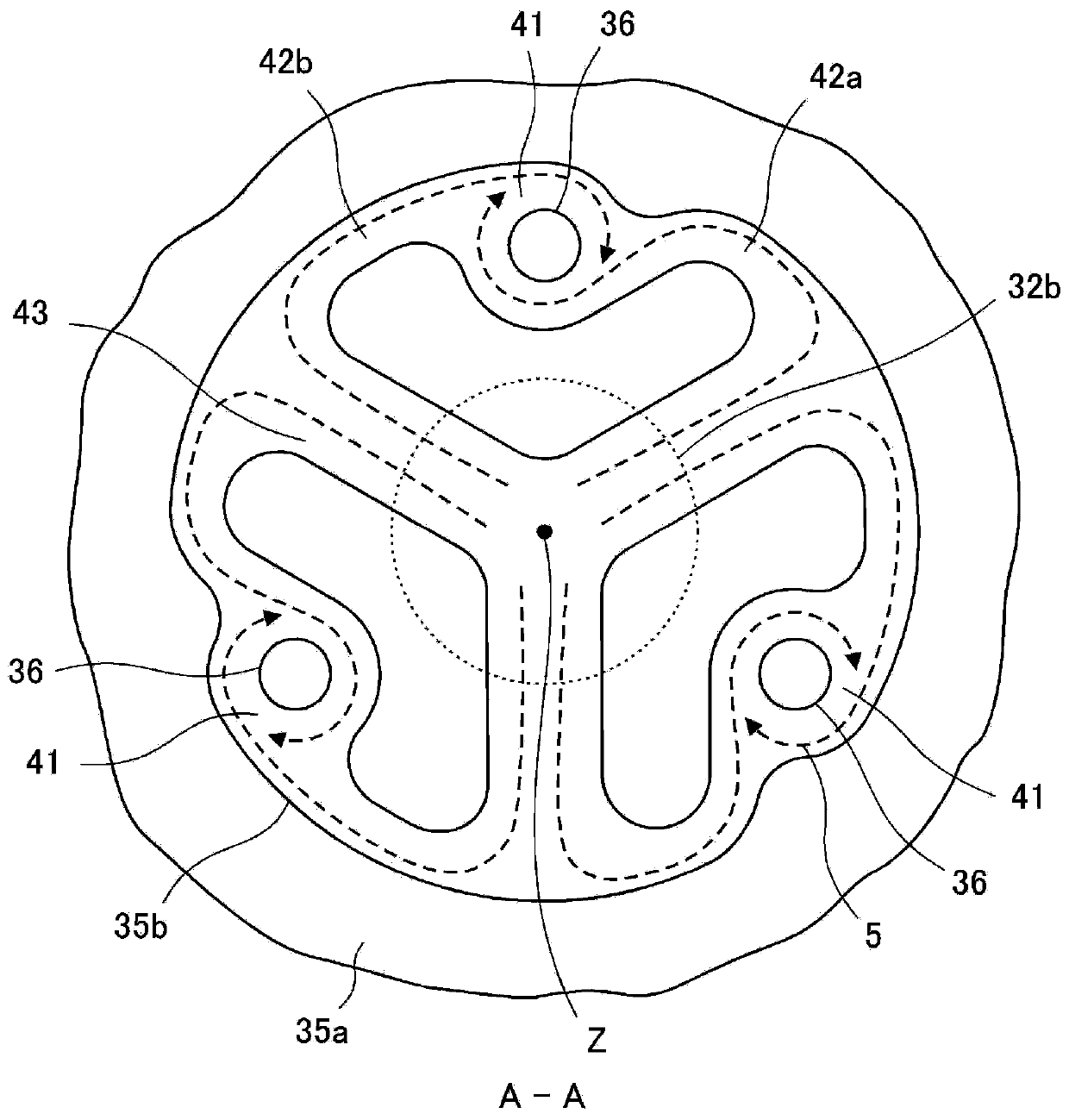
[0064]Hereinafter, the fuel injection valve according to Embodiment 1 of the present invention will be described based on the drawings. figure 1 is a cross-sectional view showing the fuel injection valve according to Embodiment 1, figure 2 is a partially enlarged cross-sectional view showing the tip portion of the fuel injection valve according to Embodiment 1, image 3 is viewed from the upstream side figure 2 The top view of the part indicated by A-A in . In addition, in each figure, the same code|symbol is attached|subjected to the same, corresponding part in a figure.
[0065] The fuel injection valve 1 includes: a solenoid device 2 that generates electromagnetic force; and a valve device 3 that operates by energizing the solenoid device 2 . The solenoid device 2 includes: a casing 21, which forms a yoke portion of a magnetic circuit; an iron core 22, which is a fixed iron core disposed inside the casing 21; a coil 23, which surrounds and an armature 24 which is a mo...
Embodiment approach 2
[0095] In this embodiment 2, use Figure 8 ~ Figure 10 , a modified example of the structure for causing a difference in the ratio of the fuel flowing into the injection hole 36 from the two swirling passages 42 will be described. In addition, since the overall structure of the fuel injection valve of the second embodiment is the same as that of the first embodiment, the figure 1 , and omit the description of each part.
[0096] exist Figure 8 In the illustrated example, the communication direction of the central axis side swirling passage 42a toward the swirling chamber 41 is more inclined to the nozzle hole center 36a than the communication direction of the outer peripheral side swirling passage 42b toward the swirling chamber 41 . Thereby, the fuel flow (arrow 5a in the figure) that flows into the swirl chamber 41 from the center axis side swirl passage 42a is the same as the fuel flow (arrow 5b in the figure) that flows into the swirl chamber 41 from the outer periphera...
Embodiment approach 3
[0103] Figure 11 The structure and fuel flow of the tip portion of the fuel injection valve according to Embodiment 3 of the present invention are shown. The fuel injection valve 1 according to Embodiment 3 includes injection holes 36A inclined with respect to the plate thickness direction of the injection hole plate 35 so that the thickness in the circumferential direction of the hollow conical fuel liquid film 51 injected from the injection hole outlet 36b does not change. Uniform means. In addition, since the overall structure of the fuel injection valve according to the third embodiment is the same as that of the above-mentioned first embodiment, the figure 1 , and omit the description of each part.
[0104] Figure 12 is viewed from the arrow side Figure 11 Sectional view of the part indicated by D-D in . Such as Figure 12 As shown, the injection hole 36A of the fuel injection valve according to Embodiment 3 is inclined toward the valve seat center axis Z side fr...
PUM
 Abstract
Description
Claims
Application Information
 - R&D
- Intellectual Property
- Life Sciences
- Materials
- Tech Scout
- Unparalleled Data Quality
- Higher Quality Content
- 60% Fewer Hallucinations
Browse by: Latest US Patents, China's latest patents, Technical Efficacy Thesaurus, Application Domain, Technology Topic, Popular Technical Reports.
© 2025 PatSnap. All rights reserved.Legal|Privacy policy|Modern Slavery Act Transparency Statement|Sitemap|About US| Contact US: help@patsnap.com


