High-efficiency air distribution system for garbage incinerator and application method thereof

A waste incinerator, high-efficiency air technology, applied in the combustion method, incinerator, combustion type and other directions, can solve the waste gas recovery operation equipment investment and operating costs increase, serious waste heat recovery work from flue gas exhaust gas, cooling water and other resources waste and other problems, to achieve the effect of reducing equipment investment costs and resource consumption, reducing operation and maintenance costs, and reducing the use of cooling systems

Active Publication Date: 2017-11-17
海诺尔环保产业股份有限公司
View PDF5 Cites 4 Cited by
  • Summary
  • Abstract
  • Description
  • Claims
  • Application Information

AI Technical Summary

Problems solved by technology

[0002] At present, in the waste incineration power generation operation, the waste incinerator often produces a large amount of high-temperature tail gas after incinerating the waste. At present, in order to improve the treatment of the tail gas and the recycling rate of resources, the tail gas is often passed through once or several times. Waste heat recovery equipment realizes the recovery and utilization of waste heat in the exhaust gas. However, in actual use, it is found that the heat exchange efficiency of the currently used waste heat recovery equipment is relatively low. When the temperature of the exhaust gas is relatively low, the waste heat in the exhaust gas cannot be effectively recovered. Therefore, when reviewing the waste heat of the exhaust gas produced by incineration of garbage, an organic Rankine cycle power generation device is introduced to recover the waste gas in the exhaust gas after passing through multiple heat exchangers. The remaining heat is recovered. However, when using the organic Rankine cycle power generation device, in order to improve the working efficiency of the organic Rankine cycle power generation device, it is often necessary to equip a large number of cooling devices. The cost has increased, and it has also led to a large waste of resources such as cooling water, and the cooling equipment currently used does not have the ability to cool down the equipment in the entire exhaust heat recovery system, resulting in the current waste heat recovery of exhaust gas. In the process, it is often easy to cause some equipment to malfunction due to excessive temperature, which seriously affects the smooth development of waste heat recovery from flue gas and tail gas. Meet the needs of actual use

Method used


Image

  • High-efficiency air distribution system for garbage incinerator and application method thereof
  • High-efficiency air distribution system for garbage incinerator and application method thereof
  • High-efficiency air distribution system for garbage incinerator and application method thereof

Examples


Embodiment Construction

[0019] In order to make the technical means, creative features, goals and effects achieved by the present invention easy to understand, the present invention will be further described below in conjunction with specific embodiments.

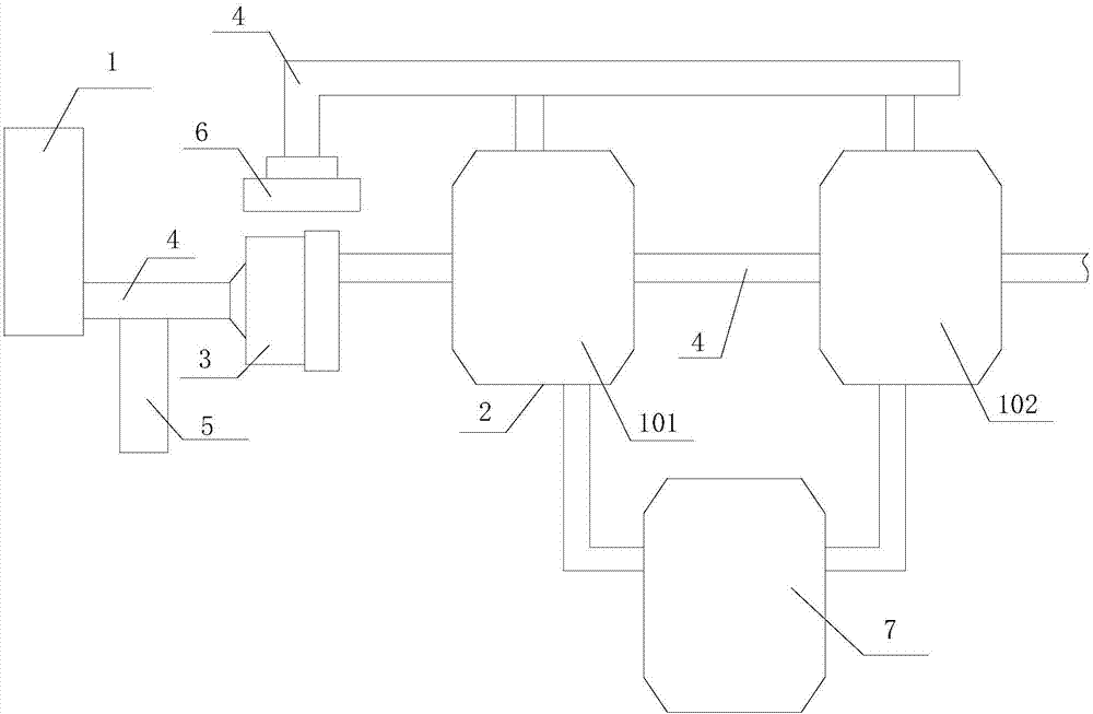
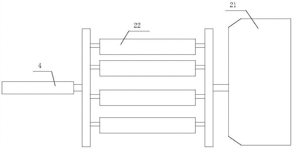
[0020] Such as Figure 1-2 As shown, a high-efficiency air distribution system for a waste incinerator includes a flue gas heat exchanger 1, a waste heat power generation unit 2 and a booster pump 3, wherein there are at least two waste heat power generation units 2, and two adjacent waste heat power generation units 2 The air ducts 4 are connected in series to form a power generation subsystem, and the waste heat power generation units 2 in the power generation The unit 101 communicates with the booster pump 3 through the air duct 4 , and the booster pump 3 communicates with the flue gas heat exchanger 1 through the air duct 4 .

[0021] In this embodiment, the waste heat power generation unit 2 includes an organic Rankine cycle power generation...


PUM


Abstract

The invention discloses a high-efficiency air distribution system for a garbage incinerator and an application method thereof. The high-efficiency air distribution system comprises a flue gas heat exchanger, at least two waste heat power generation units and a booster pump. The two adjacent waste heat power generation units are connected in series through a gas guide pipe to form a power generation subsystem. The waste heat power generation units in each power generation subsystem are called the first-stage power generation unit and the second-stage power generation unit from front to back in sequence, wherein the first-stage power generation unit communicates with the booster pump through a gas guide pipe. The booster pump communicates with the flue gas heat exchanger through a gas guide pipe. Each waste heat power generation unit comprises an organic rankine cycle power generation device and air eddy pipes. The application method of the high-efficiency air distribution system comprises the steps of equipment layout and waste heat recovery. By adopting the high-efficiency air distribution system for the garbage incinerator and the application method thereof, on one hand, waste heat of tail gas can be effectively recycled, and resource waste is avoided, and on the other hand, application of a traditional cooling system can be effectively reduced while the waste heat of the tail gas is recycled.

Description

technical field [0001] The invention relates to waste heat recovery equipment, in particular to a high-efficiency air distribution system for garbage incinerators. Background technique [0002] At present, in the waste incineration power generation operation, the waste incinerator often produces a large amount of high-temperature tail gas after incinerating the waste. At present, in order to improve the treatment of the tail gas and the recycling rate of resources, the tail gas is often passed through once or several times. Waste heat recovery equipment realizes the recovery and utilization of waste heat in the exhaust gas. However, in actual use, it is found that the heat exchange efficiency of the currently used waste heat recovery equipment is relatively low. When the temperature of the exhaust gas is relatively low, the waste heat in the exhaust gas cannot be effectively recovered. Therefore, when reviewing the waste heat of the exhaust gas produced by incineration of ga...

Claims


Application Information

Patent Timeline
Patent Type & Authority Applications(China)
IPC IPC(8): F23G5/46F23J15/02F01K27/00
Inventor 骆毅力骆的杨伦洲杨大利
Owner 海诺尔环保产业股份有限公司
Why Eureka
Try Eureka