Lens coupling apparatus, structure and method based on flat window type TO package

A technology of a coupling device and a coupling structure, which is applied to the coupling of optical waveguides and other directions, can solve problems such as bad and the lens cannot be dynamically adjusted, and achieve the effect of improving the coupling accuracy.

Active Publication Date: 2017-11-17
GUANGXUN SCI & TECH WUHAN
View PDF10 Cites 8 Cited by
  • Summary
  • Abstract
  • Description
  • Claims
  • Application Information

AI Technical Summary

Problems solved by technology

[0006] The technical problem to be solved by the present invention is that in the existing flat-window TO package, due to the dimensional tolerances of TO internal components, external components and component assembly tolerances, the focal length of each device is different, and the output optical power of the laser is different. For applications with higher requirements, the position of the lens in the device cannot be dynamically adjusted in the prior art, and it cannot be guaranteed that each device can achieve a high coupling efficiency, and the coupling consistency of the device is not good

Method used


Image

  • Lens coupling apparatus, structure and method based on flat window type TO package
  • Lens coupling apparatus, structure and method based on flat window type TO package
  • Lens coupling apparatus, structure and method based on flat window type TO package

Examples


Embodiment 1

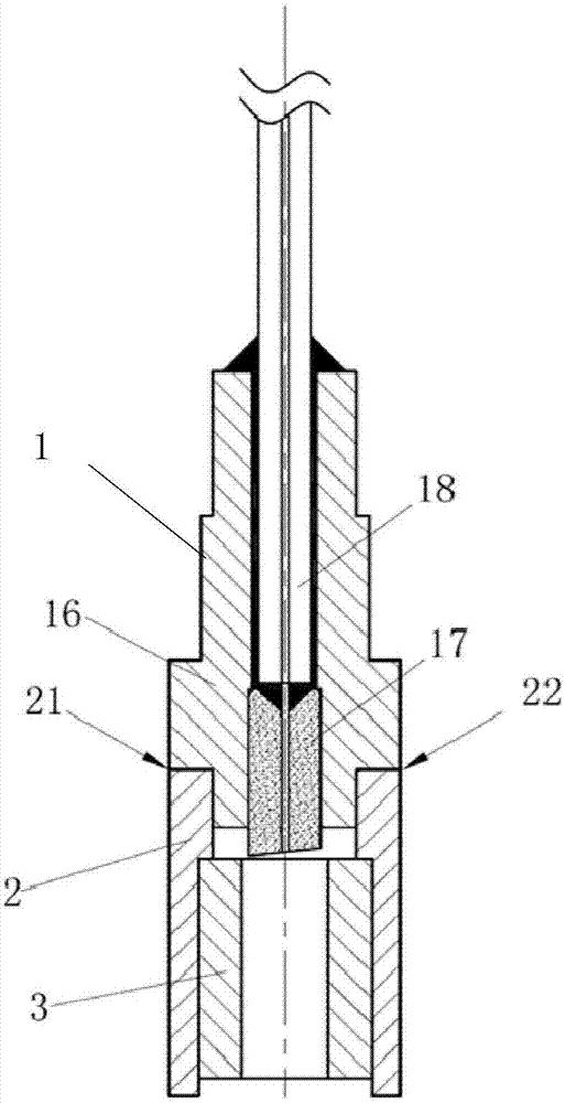
[0043] Embodiment 1 of the present invention provides a lens coupling device based on a flat-window TO package, such as figure 1As shown, the lens coupling device includes: a lens coupling pigtail 1, a coupling sleeve 2, and a magnetic ring 3, wherein the lens coupling device can be applied to the processing of flat-window TO-packaged lasers, and can also be applied to the Fabrication of photodetectors in flat-window TO packages. The lens coupling device is used as a grabbing part of a lens element 4 during specific use, and the lens coupling device can also be completed by using the test equipment connected to the pigtail 18 after grabbing the lens element 4 The lens couples the optical path to align for the final soldering process. Next, the connection structure between the constituent elements included in the lens coupling device will be described in detail.

[0044] Such as figure 1 As shown, the lens coupling pigtail 1 is composed of a metal jacket 16 and a ceramic fer...

Embodiment 2

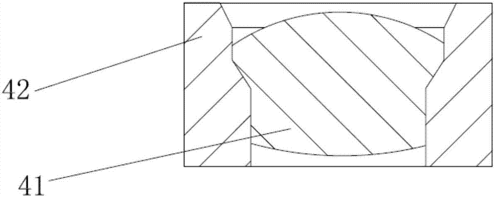
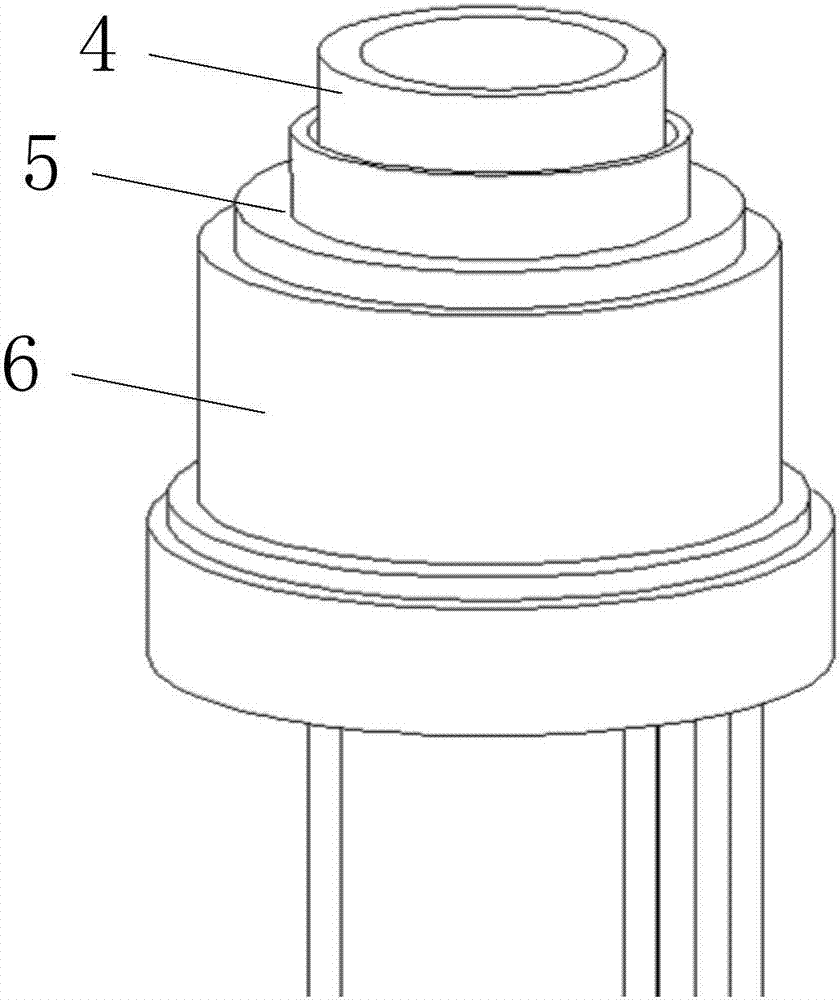
[0054] The existence value of the embodiment of the present invention is the lens coupling structure (that is, the flat window TO packaged optical device) that can be used as a supporting device for the lens coupling device described in Embodiment 1. Such as image 3 As shown, it is a lens coupling structure based on a flat-window TO package proposed by an embodiment of the present invention, including a lens element 4, a lens coupling adjustment ring 5, and a flat-window TO6. The lens element 4 includes an aspheric lens 41 and The peripheral metal 42, the aspherical lens is press-fitted inside the peripheral metal 42, and the material of the peripheral metal 42 is stainless steel with certain magnetic properties;

[0055] At least three laser welding spots are arranged between the lens coupling adjustment ring 5 and the outer diameter of the peripheral metal 42 of the lens element 4, wherein the peripheral metal 42 is set at the upper and lower positions of the lens coupling ...

Embodiment 3

[0063] In the embodiment of the present invention, in addition to providing the lens coupling device described in Embodiment 1 and the lens coupling structure described in Embodiment 2, a lens coupling method based on a flat-window TO package is provided, and the lens coupling Applied to the lens coupling device described in embodiment 1 and the lens coupling structure described in embodiment 2 in the method, such as Figure 4 and Figure 5 As shown, the coupling method specifically includes the following execution steps:

[0064] In step 201, the coupling device including the lens coupling pigtail 1, the coupling sleeve 2 and the magnetic ring 3 is installed on the coupling fixture.

[0065] Wherein, the coupling jig can be an existing jig, and the existing jig usually has fine-tuning functions in the X-axis, Y-axis and Z-axis directions, and when used in conjunction with the lens coupling device proposed in Embodiment 1 of the present invention, It only needs to fix the le...


PUM

PropertyMeasurementUnit
Diameteraaaaaaaaaa

Abstract

The invention relates to the technical field of optical devices, and provides a lens coupling apparatus, structure and method based on a flat window type TO package. The lens coupling apparatus comprises a lens coupling tail fiber, a coupling sleeve and a magnet ring, the lens coupling tail fiber is formed by a metal outer sleeve and a ceramic ferrule, the ceramic ferrule is arranged at the internal part of the metal outer sleeve in a pressed manner, another port of the tail fiber on the ceramic ferrule is used for connecting test equipment, the coupling sleeve sleeves a step of the metal outer sleeve, the coupling sleeve and the metal outer sleeve are in clearance fit and fixed through laser beam welding, and the lower surface of the magnet ring is used for designing a magnetic force mutual coupling structure with the upper surface of peripheral metal of a lens element. According to the apparatus, structure and method, position adjustment of the lens element on the flat window type TO is driven through the magnetic adsorption type coupling mode between the magnet ring and the peripheral metal of the lens element, and after a preset lens coupling optical path aligning index requirement is met, the welding operation between coupling interfaces is completed.

Description

【Technical field】 [0001] The invention relates to the technical field of optical devices, in particular to a lens coupling device, a coupling structure and a coupling method based on a flat-window TO package. 【Background technique】 [0002] For optical devices in the field of optical communications, TO packaging has the advantages of simple process, low cost, and convenient use. At the current 10G or even 25G rate, TO packaging has been widely used. The role of the lens in the TO device is to ensure the coupling efficiency between the optical chip and the optical fiber. At present, the common TO is divided into lens type TO and flat window type TO. [0003] Lensed TO is an aspherical lens or ball lens integrated on the TO cap, this type of TO can be directly used for coupling with optical fiber. This type of TO with a lens has two disadvantages. One: because the position of the lens on the TO cap has been fixed, considering the dimensional tolerance of the internal compone...

Claims


Application Information

Patent Timeline
IPC IPC(8): G02B6/32
CPCG02B6/32
Inventor 阮扬徐红春刘成刚
Owner GUANGXUN SCI & TECH WUHAN
Why Eureka
Try Eureka