Image, spectrum and polarization state integration acquisition device and detection method

A technology for acquiring device and polarization state, applied in the field of imaging, can solve the problems of inability to remove by filtering algorithm, crosstalk phenomenon, affecting restored spectral resolution, etc. The effect of low noise ratio

Active Publication Date: 2017-11-21
XI AN JIAOTONG UNIV
7 Cites 12 Cited by

AI-Extracted Technical Summary

Problems solved by technology

However, the interference image obtained by using CSP technology needs to perform channel filtering of the optical path difference dimension when restoring the polarization spectrum information. This process reduces the optical path difference corresponding to each channel to 1/7~1/ 3. According to the principle of Fourier transform spectroscopy, the resolution of the restored spectrum will be reduced to 1/7~1/3 of the spectral resolution of the spectrometer, which...

Abstract

The invention discloses an image, spectrum and polarization state integration acquisition device and detection method, along an incident light propagation direction, a front telescoping system, an achromatic lambda/4 wave plate array, a polarizer, a Savart polariscope, an analyzer, an imaging lens array and an area array CCD are arranged in sequence in a main optical axis direction, four kinds of modulation is performed on spectrum and polarization information through the achromatic wave plate array, then four intensity spectrum interference images after modulation are obtained through a polarized interferometer formed by the polarizer, Savart polariscope and analyzer, and a target image, and spectrum and polarization state information are precisely restored through Fourier transformation. The defects that the restored spectrum resolution is seriously reduced in measurement of a Stokes vector spectrum by a channel spectrum technology and error distortion exists in the restored spectrum are overcome. A polarization spectrum information restoration result has immunization to Gaussian noise and Poisson noise existing in an instrument, the signal-to-noise ratio of acquired interferogram data is improved, and the problems of low signal-to-noise ratio and poor timeliness in spectrum element time-sharing detection by a conventional measurement method are solved.

Application Domain

Interferometric spectrometryPolarisation spectroscopy

Technology Topic

Image

  • Image, spectrum and polarization state integration acquisition device and detection method
  • Image, spectrum and polarization state integration acquisition device and detection method
  • Image, spectrum and polarization state integration acquisition device and detection method

Examples

  • Experimental program(1)

Example Embodiment

[0041] The present invention will be described in further detail below in conjunction with the accompanying drawings:
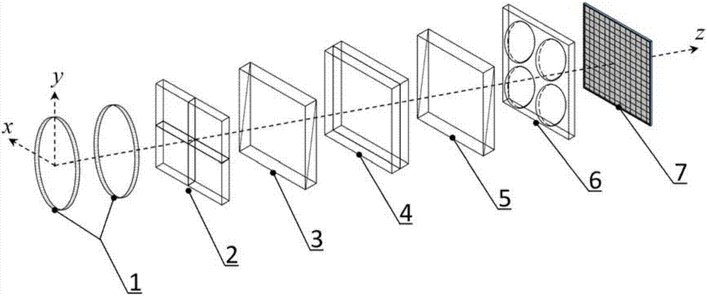
[0042] See figure 1 , The integrated acquisition device for image, spectrum, and polarization state of the present invention is provided with a front telephoto system 1, achromatic in sequence along the main optical axis of the incident light Wave plate array 2, polarizer 3, Savart polarizer 4, analyzer 5, imaging lens array 6 and CCD detector 7; construct an xyz coordinate system, the main optical axis of the incident light is the Z axis, and the xyz coordinate system satisfies the right hand Rule.
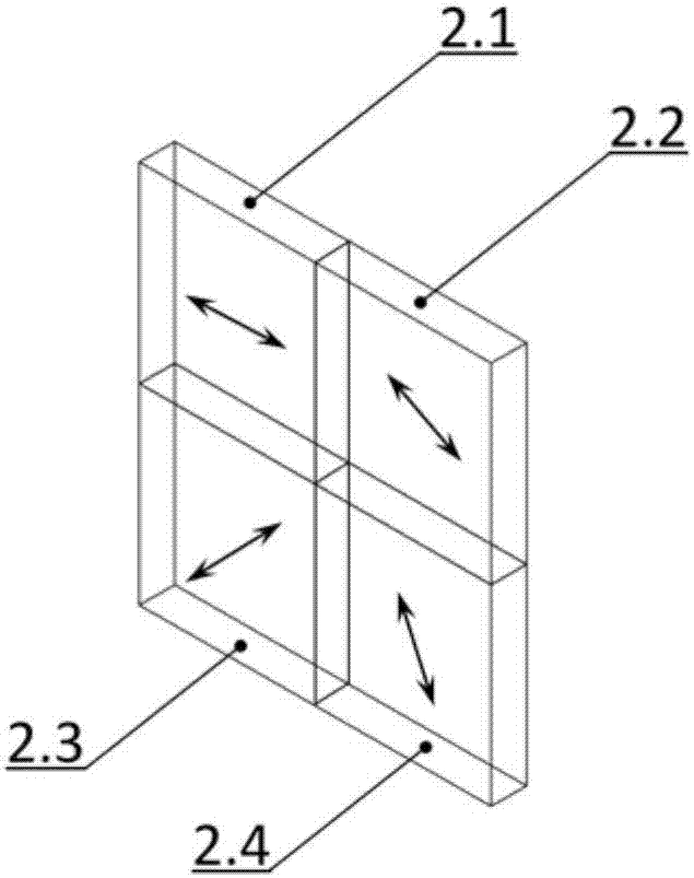
[0043] Such as figure 2 , Achromatic The wave plate array 2 includes the first achromatic Wave plate 21, second achromatic Wave plate 22, third achromatic Wave plate 23 and fourth achromatic Wave plate 24, first achromatic Fast axis direction of wave plate 21, second achromatic Fast axis direction of wave plate 22, third achromatic The fast axis direction of the wave plate 23 and the fourth achromatic The included angles between the fast axis direction of the wave plate 24 and the positive x axis are 0°, 30°, -45°, and 60°, respectively.
[0044] The angle between the transmission direction of the polarizer 3 and the positive x-axis is 0°; the optical axis of the left plate of the Savart polarizer 4 is located at an angle of 45° with the z-axis, formed in the positive y-axis and the positive x-axis The projection in the plane and the positive x-axis form an angle of 45°; the optical axis of the right plate of the Savart polarizer 4 is located at an angle of 45° with the z-axis, in the plane formed by the positive y-axis and the negative x-axis The projection forms an angle of -45° with the positive x-axis; the angle between the vibration transmission direction of the analyzer 5 and the positive x-axis is 0°.
[0045] Such as image 3 As shown: the imaging lens array 6 includes a first imaging lens 61, a second imaging lens 62, a third imaging lens 63, and a fourth imaging lens 64. The photosensitive surface of the CCD detector 7 is located on the image side focal plane of the imaging lens array.
[0046] The incident light becomes parallel light after being collimated by the front telephoto system 1, and the parallel light passes through the achromatic The wave plate array 2 and the polarizer 3 are decomposed into four beams of light with different modulation states. The four beams of light with different modulation states pass through the Savart polarizer 4, the analyzer 5 and the imaging lens array 6 and then pass through the four CCD detectors 7 The interferograms of the modulation spectrum are obtained on the quadrant area respectively.
[0047] Based on the above device, the image, spectrum, and polarization state detection method of the present invention includes the following steps:
[0048] According to the principle of polarization optics, the Stokes vector S(x,y,λ) of the beam emitted from the spatial point (x,y) is:
[0049]
[0050] Where S 0 Is the total energy of the beam, S 1 Is the difference between the intensity of linearly polarized light in the 0° direction and the linearly polarized light in the 90° direction, S 2 Is the difference between the intensity of the linearly polarized light in the 45° direction and the linearly polarized light in the 135° direction, S 3 Is the difference in intensity between right-handed circularly polarized light and left-handed circularly polarized light. (x, y) is the space coordinates of the target, and σ is the wave number of the detected target.
[0051] Achromatic The Mueller matrix of the wave plate is:
[0052]
[0053] Among them, θ is achromatic The angle between the fast axis direction of the wave plate and the positive x axis.
[0054] The Muller matrix of the polarizer array is:
[0055]
[0056] Where θ is the angle between the transmission direction of the polarizer and the positive x-axis.
[0057] The incident light is collimated and achromatic by the telephoto system 1 The wave plate array 2 and the polarizer 3 are modulated to form four beams of light with different polarization states. Among them, the polarization state of any beam is represented by the Stokes vector as [S 0 S 1 S 2 S 3 ] T , The polarization state of any beam is:
[0058]
[0059] Where θ 1 Corresponding achromatic for this beam The angle between the fast axis direction of the wave plate and the positive x axis, θ 2 It is the angle between the transmission direction of the polarizer and the positive x-axis of the beam.
[0060] When describing the spectrum and polarization information of incident light by Stokes vector, since the CCD detector 7 only responds to the total light intensity and is not sensitive to the polarization state of the light, only the S of the incident light is considered. 0 In the case of component modulation, the incident light is collimated by the front telephoto system 1 and becomes parallel light, and the parallel light passes through the achromatic The wave plate array 2 and the polarizer 3 are decomposed into four beams of light with different modulation states, and the four beams of light with different modulation states are S 0 The components are:
[0061]
[0062]
[0063]
[0064]
[0065] In the formula, σ is the wave number. The angles between the polarization directions of the four light beams in different modulation states and the positive x-axis are all 0°, and then the modulation spectrum is obtained on the four quadrant regions of the CCD detector after passing through the Savart polarizer, analyzer and imaging lens array Interferogram of:
[0066]
[0067]
[0068]
[0069]
[0070] Where Is the phase difference generated by the Savart polarizer, Δ is the optical path difference, any one of the four interferograms mentioned above is subjected to background low-pass filtering to obtain the target image. According to Fourier transform spectroscopy, the interferogram I Path1 , I Path2 , I Path3 , I Path4 Perform Fourier transform spectrum restoration, get and
[0071] All Stokes parameters of incident light pass and Revert to:
[0072]
[0073]
[0074]
[0075]
[0076] Obtain all Stokes vector spectra of incident light [S 0 S 1 S 2 S 3 ] T.
[0077] In summary, the device and method of the present invention pass achromatic The wave plate array spatially modulates the spectrum and polarization information, and the interference images of each channel are located in different spatial positions, and there is no problem of interference image aliasing. At the same time, each channel occupies the maximum optical path difference provided by the interferometer system, maintaining the original spectral resolution of the instrument, so that while maintaining the original resolution of the interference imaging spectrometer, the target can be accurately obtained through a push-scan measurement. Image, spectrum and polarization information. The acquisition of target image information is the most intuitive, and the polarization and spectrum information can be restored by performing Fourier transform and simple mathematical operations on the acquired interferogram information. Achromatic The optimized selection of the fast axis direction of the waveplate array makes the polarization spectrum restoration result immune to the Gaussian noise and Poisson noise of the instrument, and improves the signal-to-noise ratio of the interferogram data. It solves the problems of low signal-to-noise ratio and poor timeliness of spectral element time-sharing detection in conventional measurement methods, and at the same time overcomes the shortcomings of severely reduced resolution of the restored spectrum and errors in the restored spectrum in the method of measuring Stokes vector spectrum using channel spectrum technology.

PUM

no PUM

Description & Claims & Application Information

We can also present the details of the Description, Claims and Application information to help users get a comprehensive understanding of the technical details of the patent, such as background art, summary of invention, brief description of drawings, description of embodiments, and other original content. On the other hand, users can also determine the specific scope of protection of the technology through the list of claims; as well as understand the changes in the life cycle of the technology with the presentation of the patent timeline. Login to view more.

Similar technology patents

Optical delay line interferometer

ActiveUS20100119189A1High symmetryImprove signal-to-noise ratioLight demodulationElectromagnetic receiversPhysicsPolarization coupling
Owner:NIPPON TELEGRAPH & TELEPHONE CORP

Classification and recommendation of technical efficacy words

Why Eureka
Try Eureka