Eureka AIR delivers breakthrough ideas for toughest innovation challenges, trusted by R&D personnel around the world.

Tail gas treatment system

A technology for exhaust gas treatment and exhaust gas collection, which is applied in gas treatment, mechanical equipment, membrane technology, etc., can solve the problems of increased difficulty, high cost, secondary pollution and other problems of environmental governance, and achieves easy operation and maintenance, low use cost, The effect of less safety hazard

Inactive Publication Date: 2017-11-24
BEIJING FOTONDAIMLER AUTOMOTIVE
View PDF7 Cites 7 Cited by
  • Summary
  • Abstract
  • Description
  • Claims
  • Application Information

AI Technical Summary

Problems solved by technology

[0003] In related technologies, the mainstream engine exhaust treatment equipment is dual-alkali method and chemical method. The former has a low purification capacity of nitrogen oxides, and the equipment will produce secondary pollution sources such as harmful waste water and waste heat. The latter mostly uses chemicals such as strong acids to The cost of waste gas treatment is high, and a separate storage space for hazardous chemicals is required, causing secondary pollution
[0004] It is precisely because of these problems that the engine exhaust treatment equipment in the related art is not suitable for the daily operation of the engine and vehicle manufacturers. As a result, most automobile engine factories are unwilling to add exhaust treatment equipment or do not start the equipment according to the requirements after installation, thus causing environmental pollution. increased difficulty

Method used


Image

  • Tail gas treatment system
  • Tail gas treatment system
  • Tail gas treatment system

Examples


Embodiment Construction

[0039] Embodiments of the present invention are described in detail below, examples of which are shown in the drawings, wherein the same or similar reference numerals designate the same or similar elements or elements having the same or similar functions throughout. The embodiments described below by referring to the figures are exemplary only for explaining the present invention and should not be construed as limiting the present invention.

[0040] In describing the present invention, it should be understood that the terms "center", "longitudinal", "transverse", "length", "width", "thickness", "upper", "lower", "front", " Back", "Left", "Right", "Vertical", "Horizontal", "Top", "Bottom", "Inner", "Outer", "Axial", "Radial", "Circumferential", etc. The indicated orientation or positional relationship is based on the orientation or positional relationship shown in the drawings, and is only for the convenience of describing the present invention and simplifying the description,...


PUM


Abstract

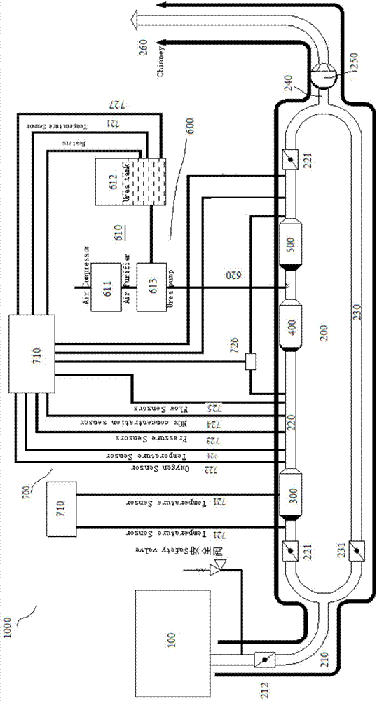
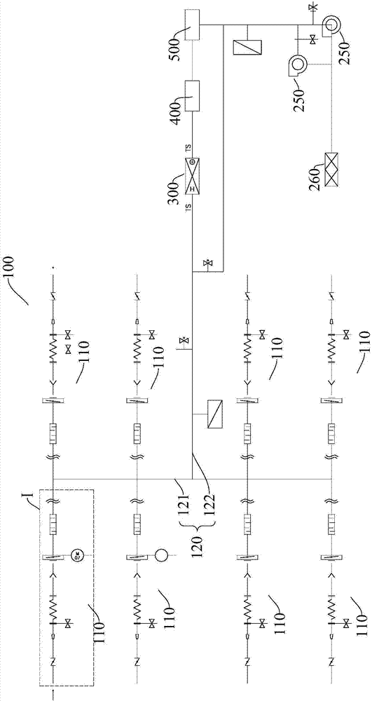
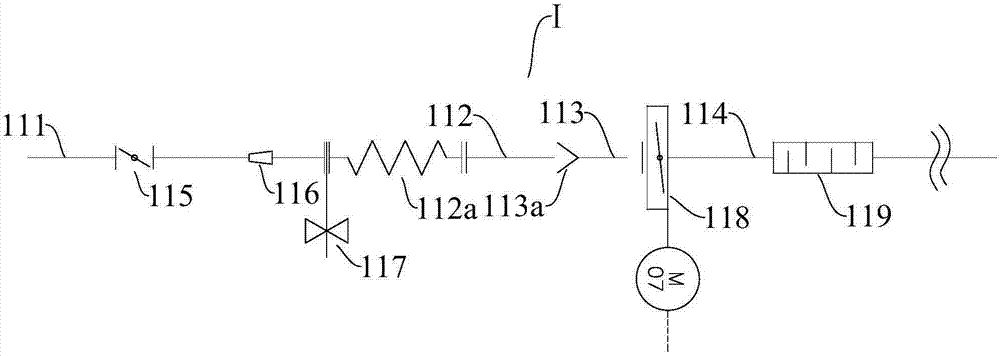
The invention discloses a tail gas treatment system. The tail gas treatment system comprises a tail gas collection device for collecting tail gas, a tail gas treatment pipeline of which the gas inlet end is connected with the gas outlet end of the tail gas collection device, a temperature compensation unit arranged on the tail gas treatment pipeline, a catalytic oxidation unit, a selective catalytic reduction unit, a reductant supply unit and a control unit connected with the temperature compensation unit and the reductant supply unit, wherein the catalytic oxidation unit and the selective catalytic reduction unit are sequentially connected in series with the interior of the tail gas treatment pipeline; and the outlet of the reductant supply unit is communicated with the tail gas treatment pipeline, and the communication part is positioned on the front side of the selective catalytic reduction unit. The tail gas treatment system can conveniently treat tail gas emitted by an engine in a centralized manner, can not cause secondary pollution in the treatment process, only needs to replenish a reductant in the long-term use process, and is low in using cost and easy to operate and maintain.

Description

technical field [0001] The invention belongs to the technical field of tail gas treatment, and in particular relates to a tail gas treatment system. Background technique [0002] Engine exhaust is a major factor of air pollution. For automobile engine factories, the engines on each stand continue to work during the production process, causing more serious pollution. The environmental protection department has already released pollutants from engine factories There are quite a few restrictions. [0003] In related technologies, the mainstream engine exhaust treatment equipment is dual-alkali method and chemical method. The former has a low purification capacity of nitrogen oxides, and the equipment will produce secondary pollution sources such as harmful waste water and waste heat. The latter mostly uses chemicals such as strong acids to Disposal of waste gas is costly, requires a separate storage space for hazardous chemicals, and produces secondary pollution. [0004] It ...

Claims


Application Information

Patent Timeline
Patent Type & Authority Applications(China)
IPC IPC(8): B01D53/94B01D53/72B01D53/56B01D53/62B01D53/46
CPCB01D53/9431B01D53/944B01D53/9495B01D2251/2067B01D2258/01Y02T10/12
Inventor 王如双郑天玉马里奥·阿泰托
Owner BEIJING FOTONDAIMLER AUTOMOTIVE
Why Eureka
Eureka Blog
Learn More