Earth covered storage tank system for storing liquefied hydrocarbon at normal temperature and pressure

A technology for liquefied hydrocarbons and storage tanks, which is applied in pressure vessels, fixed-capacity gas storage tanks, and methods of container discharge, etc., can solve the problems of buried storage tanks that should not be too large in volume, high engineering costs, and difficult to construct. Achieve the effect of avoiding water damage or uneven settlement, low construction cost, and low construction difficulty

Active Publication Date: 2017-11-28
WUHAN YIYE STEEL STRUCTURE +1
View PDF2 Cites 4 Cited by
  • Summary
  • Abstract
  • Description
  • Claims
  • Application Information

AI Technical Summary

Problems solved by technology

However, buried storage tanks may be partially or completely located below the groundwater level. Even if they are located above the groundwater level, they may be submerged in rainy seasons or floods. The design should consider the buoyancy of the storage tank and the buried soil after being soaked. It is necessary to set up anti-floating tension belts to fix it on the foundation anchor pier, and the current relevant national standards also limit the volume of buried storage tanks should not be too large
In addition, when the storage tank is buried, it is necessary to excavate a deep foundation pit to build the tank pond, which is difficult to construct, has a long construction period and relatively high project cost

Method used


Image

  • Earth covered storage tank system for storing liquefied hydrocarbon at normal temperature and pressure
  • Earth covered storage tank system for storing liquefied hydrocarbon at normal temperature and pressure
  • Earth covered storage tank system for storing liquefied hydrocarbon at normal temperature and pressure

Examples


Embodiment Construction

[0035] In order to better understand the present invention, below in conjunction with embodiment and accompanying drawing, technical scheme of the present invention is described further (as Figure 1-11 shown).

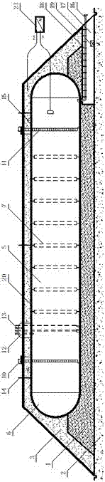
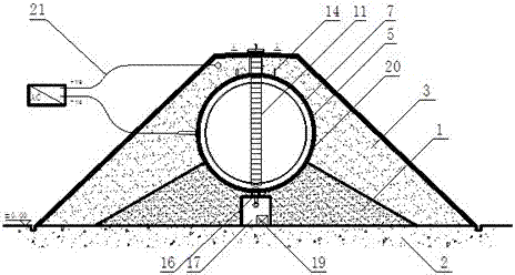
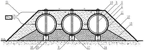
[0036] An earth-covered storage tank system for storing liquefied hydrocarbons under normal temperature and pressure, which includes one or more earth-covered storage tanks arranged side by side. Above the sand bed 1 is a flat ground 2 with uniform settlement, and the outer surface of the storage tank is completely covered by the soil layer 3; the sand bed 1 directly below each storage tank is provided with a tank bottom channel 17 (the tank bottom channel 17 is generally Constructed of concrete or reinforced concrete and normally passable for operation and maintenance);

[0037]The storage tank is a horizontal cylindrical storage tank under normal temperature and pressure, including a cylinder body 5, a spherical head 6, a reinforcement ring 7 in the tank, a manhole...


PUM

PropertyMeasurementUnit
Thicknessaaaaaaaaaa

Abstract

The invention relates to an earth covered storage tank system for storing liquefied hydrocarbon at normal temperature and pressure. The earth covered storage tank system comprises one or a plurality of earth covered storage tanks arranged side by side, wherein the storage tanks are arranged on a sand bed directly which is located above the highest underground water level, uniformly settled level ground is located below the sand bed, and the outer surface of each storage tank is totally covered with an earth covering layer; a tank bottom channel is formed in the sand bed under each storage tank; each storage tank is a normal-temperature pressure-bearing horizontal type cylindrical storage tank and comprises a cylinder body and spherical heads; a plurality of in-tank reinforcing rings are welded on the inner wall of each cylinder body; manholes, a gas chamber and settling monitoring plates are arranged at the upper part of each cylinder body; a tank bottom connecting pipe is arranged at the lower part of each cylinder body and located in the corresponding tank bottom channel; when arranged on the sand bed, each storage tank is placed obliquely towards one end of the tank bottom connecting pipe along the axis. By means of the earth covered storage tank system, BLEVE (boiling liquid expanding vapor explosion) is effectively prevented, and damage caused by approaching of a heat source, explosive shock waves and splash object impact or other sudden damage is avoided.

Description

technical field [0001] The invention relates to a soil-covered storage tank system for storing liquefied hydrocarbons under normal temperature and pressure, and belongs to the field of pressure-bearing equipment for chemical process control. Background technique [0002] Liquefied hydrocarbons, that is, petroleum hydrocarbons or mixtures, are mainly liquefied petroleum gas (LPG), including liquefied propylene, liquefied propane, liquefied n-ene, liquefied n-butane, liquefied isobutane and their mixtures. Liquefied hydrocarbons can be used not only as fuel, but also as raw materials to produce more chemical products. [0003] Petrochemical plants, refineries, storage and distribution stations, urban refueling stations, oil depots, etc. generally require a large amount of storage equipment for liquefied hydrocarbon raw materials, finished products and semi-finished products. The general operating temperature of these storage devices is about -29-60°C, and the working pressure...

Claims


Application Information

Patent Timeline
IPC IPC(8): F17C13/12F17C13/08F17C1/00
CPCF17C1/00F17C13/08F17C13/12
Inventor 夏巍郭继舟
Owner WUHAN YIYE STEEL STRUCTURE
Why Eureka
Try Eureka