Heating element cover component, heating elelment cover, radiation cooling and heating equipment, and air-conditioning system
A technology for heating elements and cover parts, which is applied to air conditioning systems, heating methods, heat sinks, etc., and can solve problems such as reduction, time-consuming, and deterioration of heat dissipation grease conduction characteristics, so as to improve heat dissipation, corrosion resistance, and efficiency effect
- Summary
- Abstract
- Description
- Claims
- Application Information
AI Technical Summary
Problems solved by technology
Method used
Image
Examples
Deformed example 1
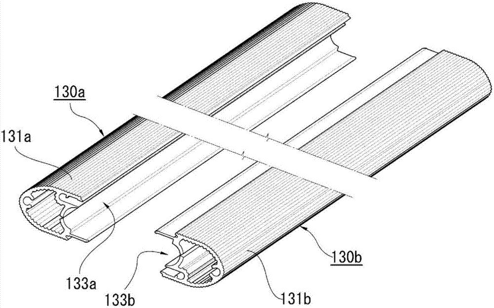
[0125] Figure 7 The heating element cover member 130f shown in (a) is a modified example of the slit of the heating element cover member. The slit 135f of the heating element cover member 130f is straightly formed in a shape having a constant width from the space 132 side toward the inner peripheral side of the contact portion 134f.
[0126] In addition, if the width of the slit is increased, the contact area with the heating element 12 will be reduced, so the width of the slit is preferably narrow. However, when the width of the slit is narrowed, the load applied to the slit-forming portion of the extrusion molding die increases, and since this portion is thin and weak, there is a possibility that the die may be damaged.
[0127]For this purpose, the width of the slit 135f may be narrowed by first forming the width of the slit to be slightly wider as in the heating element cover member 130f, and then pressing the heating element cover member 130f in the direction of the sho...
Deformed example 2
[0129] Figure 7 The heating body cover member 130g shown in (b) is a modified example of the engagement member of the engagement part. The engaging piece of the engaging portion 137g is constituted by a guide piece 191 protruding in a hook shape and a guide groove 192 having a shape capable of sliding and storing the guide piece 191 from the end surface direction. The guide piece 191 and the guide groove 192 are arranged at a line-symmetrical position with a straight line in the longitudinal direction located in the middle of the contact portion 134g in the width direction as a symmetric axis, and are a pair of members with a mutually engageable structure.
[0130] In addition, the heat generating body cover member 130g is apart from the point that the other heating body cover member 130g is mounted while sliding from the end side of one heat generating body cover member 130g when constituting the heat generating body cover. And the function is the same as that of the heatin...
Deformed example 6
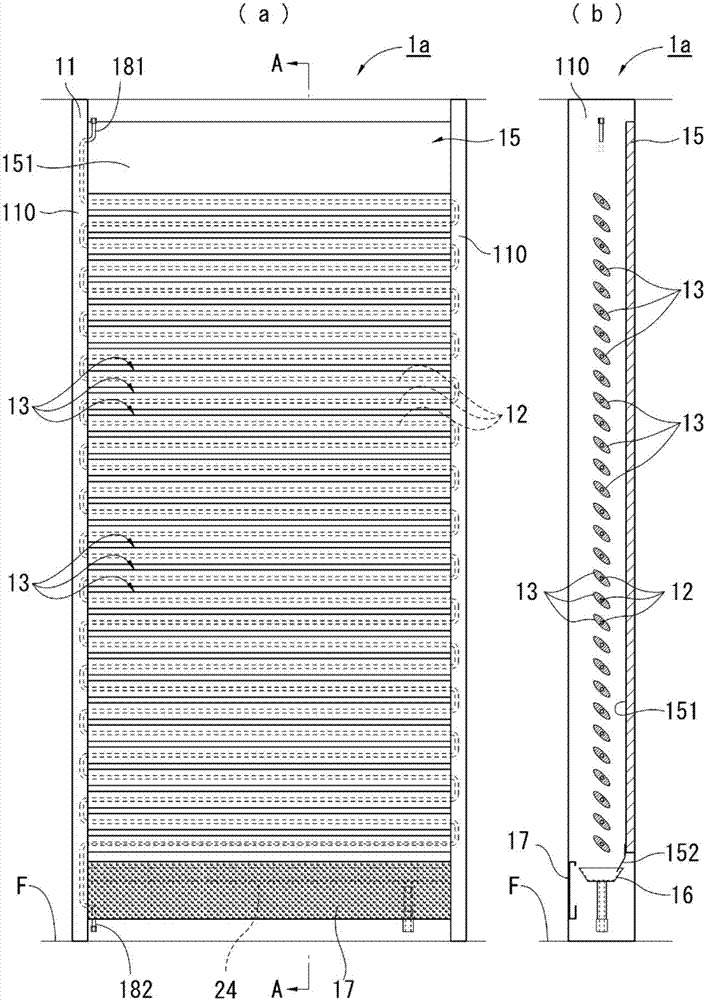
[0134] Figure 9 The radiant cooling and heating machine 1b shown is a modified example in which the heating element and the heating element cover are arranged in a vertical direction. Such as Figure 9 As shown in (b), each heating element cover 13b of the built-in heating element 12b is arranged in a figure-eight shape (or a zigzag shape) without facing each other so that the adjacent heating element covers 13b are difficult to be affected by radiant heat each other. ), through which the heat exchange efficiency can also be improved. In addition, the structure and functions of other parts are substantially the same as those of the above-mentioned radiant cooling and heating machine 1a, and therefore description thereof will be omitted.
[0135] In this embodiment, the radiant cooling / heating machine 1a is equipped with the reflector 15, but it is not limited thereto. For example, the reflective plate 15 may not be provided, so that the radiant cooling / heating machine 1a re...
PUM
 Abstract
Description
Claims
Application Information
 - R&D
- Intellectual Property
- Life Sciences
- Materials
- Tech Scout
- Unparalleled Data Quality
- Higher Quality Content
- 60% Fewer Hallucinations
Browse by: Latest US Patents, China's latest patents, Technical Efficacy Thesaurus, Application Domain, Technology Topic, Popular Technical Reports.
© 2025 PatSnap. All rights reserved.Legal|Privacy policy|Modern Slavery Act Transparency Statement|Sitemap|About US| Contact US: help@patsnap.com


