Unlock instant, AI-driven research and patent intelligence for your innovation.
Vertical radial-flow adsorber
What is Al technical title?
Al technical title is built by PatSnap Al team. It summarizes the technical point description of the patent document.
A radial flow, adsorber technology, applied in chemical instruments and methods, dispersed particle filtration, gas treatment, etc., can solve the problems of large processing flow, uneven flow steps, small footprint, etc. The effect of flow, simple structure and small footprint
Active Publication Date: 2017-12-01
NANJING UNIV OF AERONAUTICS & ASTRONAUTICS +1
View PDF5 Cites 2 Cited by
Summary
Abstract
Description
Claims
Application Information
AI Technical Summary
This helps you quickly interpret patents by identifying the three key elements:
Problems solved by technology
Method used
Benefits of technology
Problems solved by technology
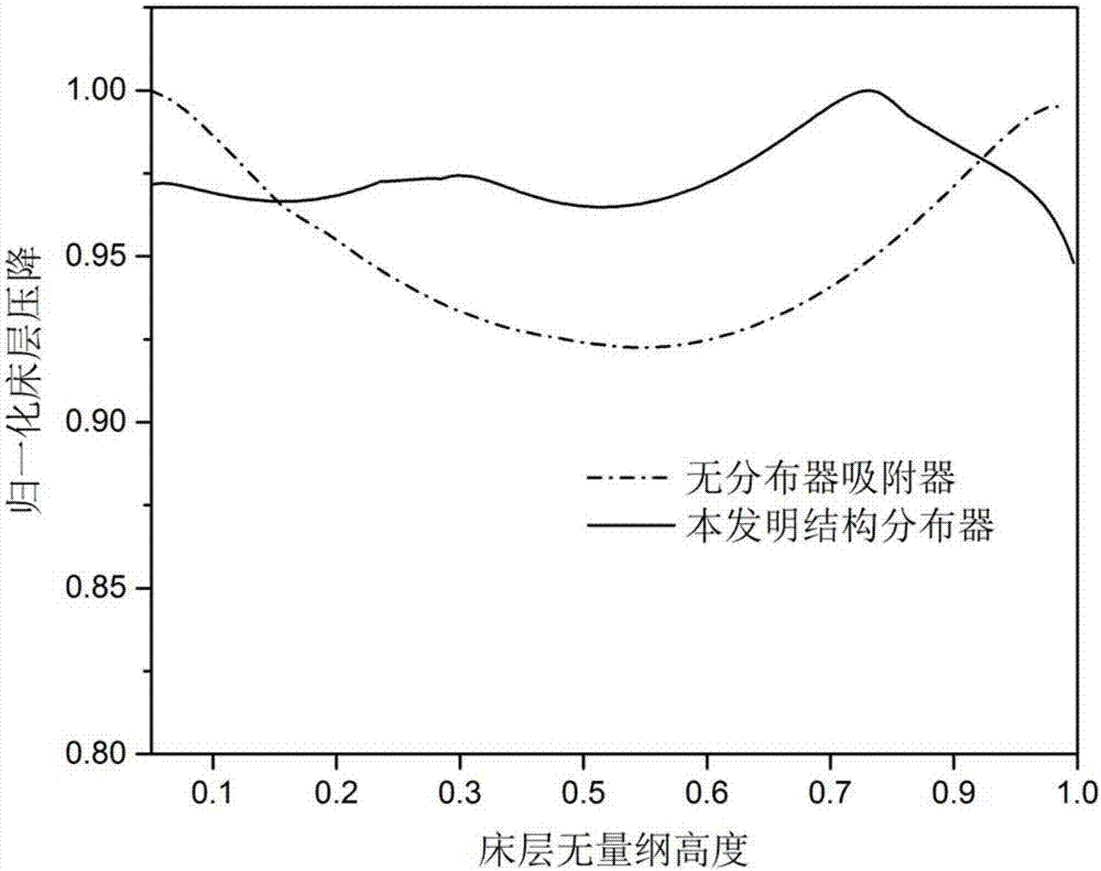
[0004] Aiming at the problem that the height of the vertical radial flow adsorber is increased, resulting in the problem that the ratio of the equivalent diameter of the adsorption bed layer to the outer annular flow channel is too large and the flow rate is not uniform, the purpose of the present invention is to provide a small footprint, Vertical radial flow adsorber with large processing flow rate and high flow field uniformity, especially suitable as a component of air separationplant in the field of cryogenic technology
Method used
Image
Click on the blue label to locate the original text in one second.
Reading with bidirectional positioning of images and text.
Examples
Embodiment 1
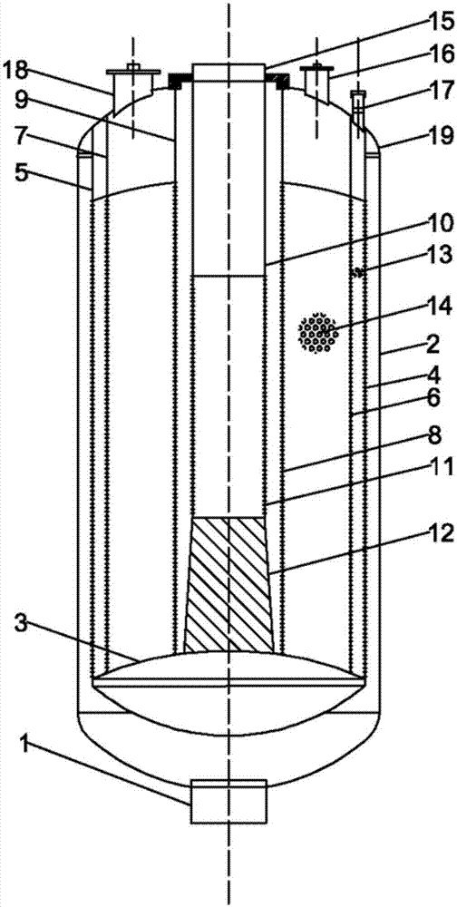
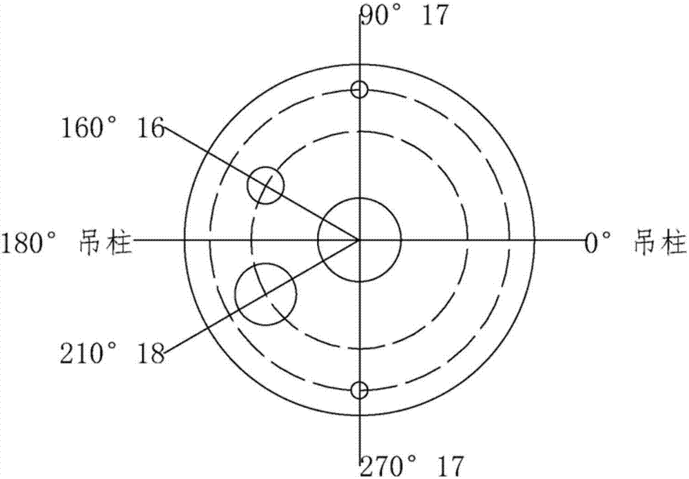
[0023] Such as figure 1 As shown, a vertical radial flow adsorber includes an inlet pipe 1, a tank body 2, a head 3, an outer cylindrical screen, a middle cylindrical screen, an inner cylindrical screen, and a central flow channel distribution Device, first adsorption bed 13, second adsorption bed 14, exhaust pipe 15, discharge port 16, two filling / discharge ports 17, manhole 18, load-bearing channel steel 19, the inlet pipe 1 is located in the tank body 2, the discharge port 16, filling / discharging port 17, manhole 18, load-bearing channel steel 19 and exhaust pipe 15 are all arranged on the upper end of the tank body 2, and the inner top of the tank body 2 hangs concentric circles Cylindrical screens are respectively the outer cylindrical screen, the middle cylindrical screen and the inner cylindrical screen, the lower end of the outer cylindrical screen, the lower end of the middle cylindrical screen and the inner cylindrical screen The lower ends of the screens are all fi...
Embodiment 2
[0025] A vertical radial flow adsorber, including an inlet pipe 1, a tank body 2, a head 3, an outer cylindrical screen, a middle cylindrical screen, an inner cylindrical screen, a central channel distributor, and a second An adsorption bed 13, a second adsorption bed 14, an exhaust pipe 15, a discharge port 16, two filling / discharge ports 17, a manhole 18, a load-bearing channel steel 19, and the air inlet pipe 1 is located at the lower end of the tank body 2 , the discharge port 16, filling / discharging port 17, manhole 18, load-bearing channel steel 19 and exhaust pipe 15 are all arranged on the upper end of the tank body 2, and a concentric cylindrical screen is suspended on the top of the tank body 2 The net is respectively the outer cylindrical screen, the middle cylindrical screen and the inner cylindrical screen, the lower end of the outer cylindrical screen, the lower end of the middle cylindrical screen and the lower end of the inner cylindrical screen are all fixed o...
PUM
Property
Measurement
Unit
porosity
aaaaa
aaaaa
Abstract
The invention discloses a vertical radial-flow adsorber. The adsorber comprises an air inlet pipe, a tank body, a spherical crown seal head, an outer cylindrical screen, a middle cylindrical screen, an inner cylindrical screen, a central flow channel distributor, a first adsorbent bed, a second adsorbent bed, an exhaust pipe, a discharge port, two feeding / discharging ports, a manhole and bearing channel steel, wherein the central flow channel distributor is located in the cavity of the inner cylindrical screen and is composed of a hollow cylinder, a porous hollow cylinder and a solid truncated cone with equal diameters. With such a structure, unfavorable influence of the height of the adsorbent beds on uniform distribution of a flow field can be reduced, and the maximum design height of the vertical radial-flow adsorber can be greatly increased. The adsorber designed in the invention has the advantages of small land occupation, low energy consumption, high flow field uniformity and the like under the condition of same treatment capacity.
Description
technical field [0001] The invention relates to the field of gas separation and purification, in particular to a vertical radial flow adsorber. Background technique [0002] At present, industrial gases are mainly obtained by air separation. Before the separation, the processing air should be pretreated with a purifier to prevent impurities such as water vapor, carbon dioxide, acetylene and other hydrocarbons from being precipitated, causing blockage or even explosion accidents. In recent years, iron and steel, metallurgy, chemical industry, aerospace and many other fields have developed rapidly, and the demand for industrial gases such as nitrogen and oxygen has increased sharply. Correspondingly, air purification equipment has been developing in the direction of large-scale and low energy consumption. Compared with other air purification equipment such as traditional vertical axial flow adsorbers and horizontal vertical flow adsorbers, vertical radial flow adsorbers ha...
Claims
Application Information
Patent Timeline
Application Date:The date an application was filed.
Publication Date:The date a patent or application was officially published.
First Publication Date:The earliest publication date of a patent with the same application number.
Issue Date:Publication date of the patent grant document.
PCT Entry Date:The Entry date of PCT National Phase.
Estimated Expiry Date:The statutory expiry date of a patent right according to the Patent Law, and it is the longest term of protection that the patent right can achieve without the termination of the patent right due to other reasons(Term extension factor has been taken into account ).
Invalid Date:Actual expiry date is based on effective date or publication date of legal transaction data of invalid patent.

