Device for purifying, treating and utilizing combustion furnace tail gas

A tail gas purification and combustion furnace technology, which is applied in the direction of combustion product treatment, combustion method, combined device, etc., can solve the problems of low heat transfer efficiency, poor purification effect of combustion furnace tail gas, unsatisfactory tail gas heat recovery effect, etc. High thermal efficiency, realize the effect of environmental protection emission

Inactive Publication Date: 2017-12-01
YANCHENG CIVIL MACHINERY CO LTD
View PDF0 Cites 2 Cited by
  • Summary
  • Abstract
  • Description
  • Claims
  • Application Information

AI Technical Summary

Problems solved by technology

[0003] The combustion furnace will produce a large amount of tail gas during the combustion of fuel. As an additional product generated during the combustion reaction, the tail gas has the characteristics of high heat. Therefore, the utilization of the combustion furnace tail gas is a major trend at present. In the combustion furnace tail gas Contains more toxic and harmful substances such as carbon monoxide and sulfur dioxide, and inhalable particulate matter such as dust particles. The existing combustion furnace tail gas treatment device has an unsatisfactory heat recovery effect on the tail gas, and the heat transfer efficiency is low. The purification effect on the combustion furnace tail gas is relatively low. Difference

Method used


Image

  • Device for purifying, treating and utilizing combustion furnace tail gas
  • Device for purifying, treating and utilizing combustion furnace tail gas

Examples


Embodiment Construction

[0017] Below in conjunction with specific embodiment, the technical scheme of this patent is described in further detail:

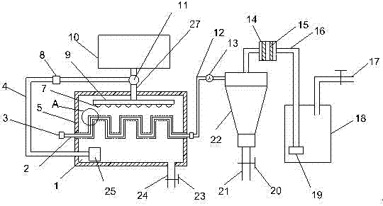
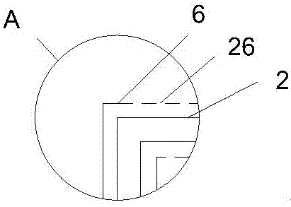
[0018] see Figure 1-2 , a combustion furnace tail gas purification treatment utilization device, including a heat exchange chamber 1, characterized in that, the bottom of the heat exchange chamber 1 is provided with a hot water pipe 24, the hot water pipe 24 is installed with a second gate valve 23; the heat exchange chamber 1 The outer surface is covered with thermal insulation cotton 5, and the heat exchange chamber 1 is provided with a curved serpentine pipe 2, and the left end of the serpentine pipe 2 is provided with an air inlet 3, and the air inlet 3 is located outside the heat exchange chamber 1; A casing 6 is provided on the outside of the shaped tube 2, and several heat exchange leakage holes 26 are evenly opened on the surface of the casing 6. A water distribution tray 9 is arranged in the heat exchange chamber 1, and a plurality of nozzles 7 ...


PUM

PropertyMeasurementUnit
thicknessaaaaaaaaaa

Abstract

The invention provides a device for purifying, treating and utilizing combustion furnace tail gas. The device comprises a heat exchange chamber and is characterized in that the outer surface of the heat exchange chamber is covered with heat preservation cotton; a bent coiled pipe is arranged in the heat exchange chamber; a gas inlet is formed in the left end of the coiled pipe; a casing pipe is sleeved outside the coiled pipe; a plurality of heat exchange leakage holes are uniformly formed in the surface of the casing pipe; a water distribution plate is arranged in the heat exchanger chamber; a plurality of nozzles are arranged at the bottom of the water distribution plate; the right end of the coiled pipe is communicated with a pressurizing pipe; a pressurizing fan is mounted on the pressurizing pipe; a cyclone separator is mounted at the right end of the pressurizing pipe; a conveying pipe is arranged at the top of the cyclone separator; a filtering box is mounted on the conveying pipe; a plurality of filtering screens are arranged in the filtering box. According to the device, the combustion furnace tail gas with characteristics of high temperature and high heat is capable of heating the casing pipe in the coiled pipe and exchanging heat with running water; the bent coiled pipe is capable of prolonging the staying time of the tail gas in the heat exchanger, so that the running water can be fully heated; higher heat transfer efficiency is achieved.

Description

technical field [0001] The invention relates to the technical field of environmental protection machinery and equipment, in particular to a device for purification, treatment and utilization of exhaust gas from a combustion furnace. Background technique [0002] Combustion furnace, electric arc combustion furnace, also known as carbon-sulfur combustion furnace, or electric arc furnace for short, uses a high-voltage, high-frequency oscillating circuit to form an instantaneous large current to ignite the sample, and the mixed gas produced after the sample burns rapidly under oxygen-enriched conditions. The chemical analysis program is an equipment that can quantitatively and quickly analyze the carbon and sulfur content in the sample. It is the crystallization of many years of hard work by Chinese physicists. [0003] The combustion furnace will produce a large amount of tail gas during the combustion of fuel. As an additional product generated during the combustion reaction, ...

Claims


Application Information

Patent Timeline
Patent Type & Authority Applications(China)
IPC IPC(8): F28D1/047B01D50/00B01D53/00F23J15/02F23J15/06
CPCB01D53/00F23J15/02F23J15/025F23J15/06F28D1/0477F23J2215/20F23J2217/10F28D21/0003B01D50/20Y02E20/30
Inventor 汤巧干
Owner YANCHENG CIVIL MACHINERY CO LTD
Why Eureka
Try Eureka