Instrument landing system gliding line check system based on unmanned aerial vehicle

An instrument landing system and unmanned aerial vehicle technology, applied in the direction of instruments, measuring devices, etc., can solve the problems of expensive calibration process, difficulty in providing accurate navigation information, and low measurement accuracy, so as to save personnel consumption, test The effect of convenience, speed and simplification of test procedures

Inactive Publication Date: 2017-12-01
CIVIL AVIATION UNIV OF CHINA
View PDF2 Cites 12 Cited by
  • Summary
  • Abstract
  • Description
  • Claims
  • Application Information

AI Technical Summary

Problems solved by technology

[0004] One is to check the glide line of the instrument landing system through ground measurement equipment, such as a portable navigation glide line signal measurement analyzer, but due to the influence of site conditions, man-made obstacles, and electromagnetic interference, it is difficult To ensure that accurate navigation information can be provided to the aircraft in the air. The measurement accuracy of this calibration method is not high, so actual flight calibration is required
[0005] The other is to use real aircraft for flight inspection. The entire flight inspection process is complicated and must be reported to relevant departments for approval, deploying aircraft and arranging flight inspection crews, applying for routes, formulating flight plans, and implementing various service guarantees for flight inspections. and a series of work, and requires the close cooperation of the flight inspection crew and ground personnel. Although this method is more accurate and reliable for flight inspection, the entire inspection process is expensive, time-consuming and laborious, and the glide line inspection is difficult. periodic inspection requirements, making it difficult to meet

Method used


Image

  • Instrument landing system gliding line check system based on unmanned aerial vehicle
  • Instrument landing system gliding line check system based on unmanned aerial vehicle

Examples


Embodiment Construction

[0015] The UAV-based instrument landing system glideline verification system provided by the present invention will be further described in detail below in conjunction with the accompanying drawings and specific embodiments.

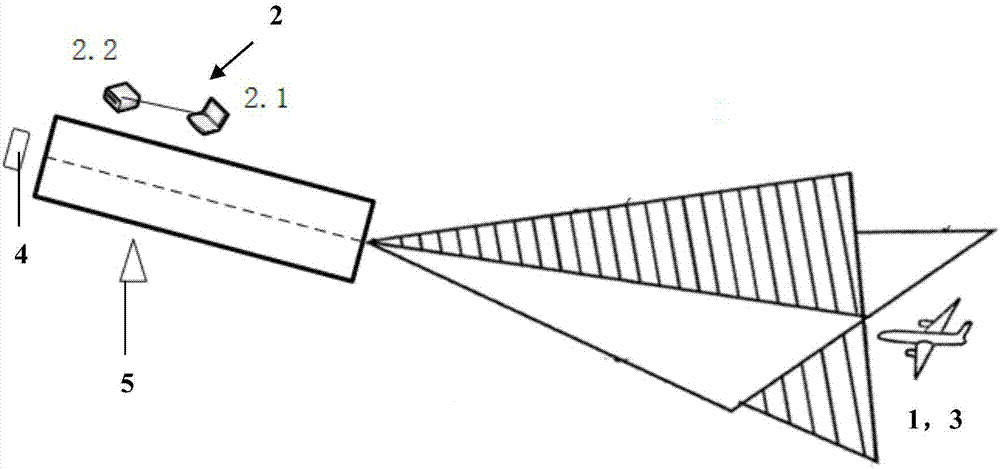
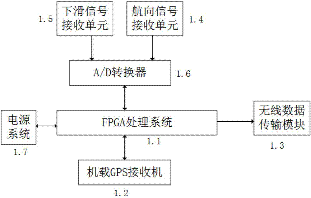
[0016] like figure 1 , figure 2 As shown, the UAV-based instrument landing system glideline verification system provided by the present invention includes an airborne system 1, ground facilities 2 and a UAV 3; wherein, the airborne system 1 is arranged on the UAV 3 Above, including FPGA processing system 1.1, airborne GPS receiver 1.2, wireless data transmission module 1.3, heading signal receiving unit 1.4, glide signal receiving unit 1.5, A / D converter 1.6, power supply system 1.7; among them: FPGA processing system 1.1 Connect with airborne GPS receiver 1.2, wireless data transmission module 1.3, A / D converter 1.6, power supply system 1.7 respectively, heading signal receiving unit 1.4, glide signal receiving unit 1.5 are connected with A / D converte...


PUM


Abstract

An instrument landing system gliding line check system based on an unmanned aerial vehicle comprises an airborne system, ground facilities and the unmanned aerial vehicle. The airborne system comprises a FPGA (field programmable gate array) processing system, an airborne GPS (global positioning system) receiver, a wireless data transmission module, a course signal receiving unit, a gliding signal receiving unit, an A/D converter and a power source system, and the ground facilities include a ground monitoring station and a data transmission base station. Ground measuring equipment is adopted to improve inaccuracy of instrument landing system gliding line check, the gliding process of a real airplane guided by navigation signals is simulated through the fixed-wing unmanned aerial vehicle, and real-time gliding position information of the airplane is positioned through the airborne GPS receiver, so that the process when the real airplane approaches can be simulated, each index of gliding lines of an instrument landing system can be checked, testing programs are simplified, all testing check tasks can be completed by only one person, testing is more convenient and quicker, and a lot of expenditure and personnel consumption can be saved for primary check of equipment.

Description

technical field [0001] The invention belongs to the technical field of air traffic control, in particular to an instrument landing system glideline verification system based on an unmanned aerial vehicle. Background technique [0002] The glide line calibration of the instrument landing system refers to the calibration, inspection and evaluation of various indicators of the glide line of the instrument landing system in accordance with the relevant specifications of the flight calibration by using an aircraft equipped with special calibration equipment to ensure the safety of the aircraft. The department provides the basis and reference for the calibration and maintenance of the instrument landing system. [0003] The current ILS glide line calibration methods include the following: [0004] One is to check the glide line of the instrument landing system through ground measurement equipment, such as a portable navigation glide line signal measurement analyzer, but due to th...

Claims


Application Information

Patent Timeline
Patent Type & Authority Applications(China)
IPC IPC(8): G01C25/00
CPCG01C25/00
Inventor 侯启真薛荣荣
Owner CIVIL AVIATION UNIV OF CHINA
Why Eureka
Try Eureka