Graphene ultra wideband planar monopole antenna
A monopole antenna, graphene technology, applied in the direction of antenna, antenna parts, antenna grounding device, etc., can solve problems such as graphene antenna research, and achieve the effect of high gain
- Summary
- Abstract
- Description
- Claims
- Application Information
AI Technical Summary
Problems solved by technology
Method used
Image
Examples
Embodiment 1
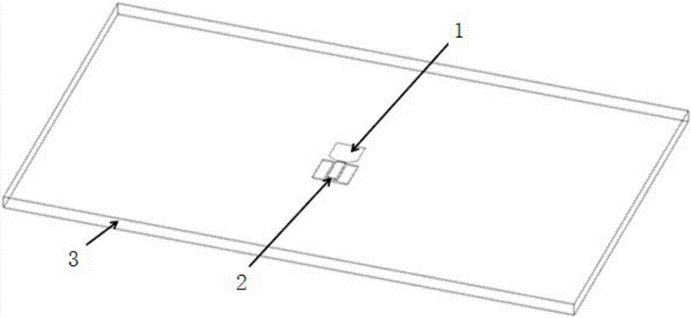
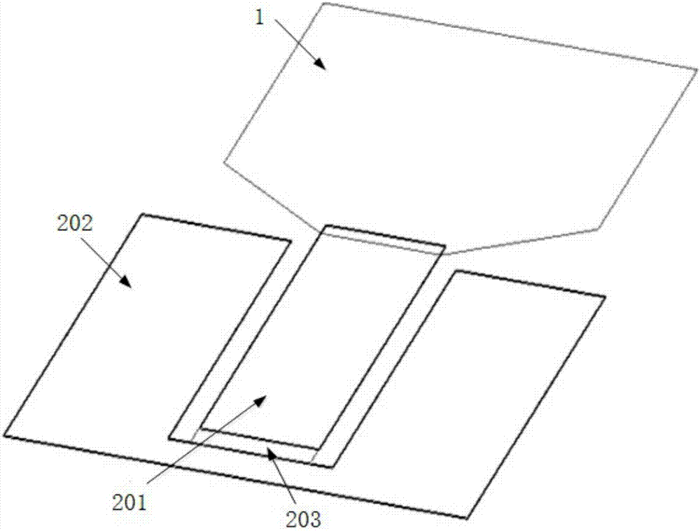
[0034] Such as figure 1 As shown, the graphene ultra-wideband planar monopole antenna (antenna one) provided by the present embodiment, antenna one can be used in wireless communication systems such as the terahertz frequency band, and the size of the planar monopole antenna is determined by the minimum operating frequency. The minimum operating frequency of the antennas involved in the article is 0.15THz. If the operating frequency changes, the size of the antenna should also be changed accordingly. According to the relationship between graphene conductivity and frequency, this antenna can work in the low terahertz frequency band. In this invention, the bias voltage of graphene is 0.5eV.
[0035] Antenna 1 mainly includes a graphene radiator 1 , a coplanar waveguide 2 and a dielectric substrate 3 , and the graphene radiator 1 and the coplanar waveguide 2 are jointly arranged on the dielectric substrate 3 . The dielectric substrate 3 is fused quartz with a volume of 3000 μm*...
Embodiment 2
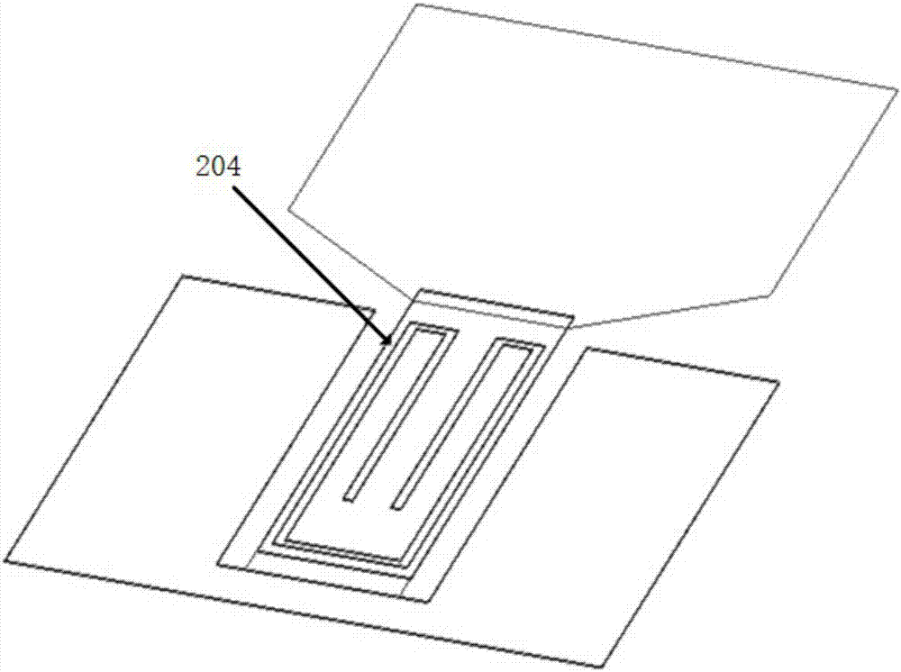
[0038] Such as image 3 As shown, the graphene ultra-wideband planar monopole antenna (antenna two) provided in this embodiment is based on the first embodiment, and based on the principle of resonance filtering, slots are made on the signal line 201 to achieve the purpose of trapping, and the trapped The wave frequency band is 0.122 THz, and the total length of the slot 204 is about half of the wavelength of the trapped frequency band. When the notched frequency band changes, the length of the slot 204 will also change. In this embodiment, the total length of the groove 204 is 880 μm, and the width is 5 μm.
Embodiment 3
[0040] Such as Figure 4 As shown, the graphene ultra-wideband planar monopole antenna (antenna three) provided by the present embodiment is based on the first embodiment or the second embodiment, and the working wavelength of the antenna is approximately around the graphene radiator 1 and the coplanar waveguide 2 A metal strip 4 is placed on half of the place, the metal strip 4 is made of gold, the width is about half of the working wavelength of the antenna, and the thickness is 1 μm. The function of the metal strip 4 is to block a large amount of energy on the dielectric substrate 3 in the metal strip 4, and the metal strip 4 also functions as an array, thereby improving the directivity and gain performance of the antenna. In this embodiment, the width of the metal strip 4 is 386 μm.
[0041] Figure 5 is the gain pattern of antenna 1 at a frequency of 0.15THz, Figure 6 is the gain pattern of antenna 1 at a frequency of 0.2THz, from Figure 5 and Figure 6 It can be s...
PUM
| Property | Measurement | Unit |
|---|---|---|
| Total length | aaaaa | aaaaa |
| Thickness | aaaaa | aaaaa |
| Length | aaaaa | aaaaa |
Abstract
Description
Claims
Application Information
 - R&D
- Intellectual Property
- Life Sciences
- Materials
- Tech Scout
- Unparalleled Data Quality
- Higher Quality Content
- 60% Fewer Hallucinations
Browse by: Latest US Patents, China's latest patents, Technical Efficacy Thesaurus, Application Domain, Technology Topic, Popular Technical Reports.
© 2025 PatSnap. All rights reserved.Legal|Privacy policy|Modern Slavery Act Transparency Statement|Sitemap|About US| Contact US: help@patsnap.com


