Eureka AIR delivers breakthrough ideas for toughest innovation challenges, trusted by R&D personnel around the world.

Synchronizer, synchronization method and high-speed receiver by using synchronizer

A synchronization device, high-speed technology, applied in the direction of synchronization device, synchronization receiver, synchronization error correction, etc., can solve the problem of receiver unable to complete ranging and communication, unable to signal synchronization, difficult signal synchronization, etc., to reduce the processing burden , reduce requirements and ensure the effect of accuracy

Active Publication Date: 2017-12-01
BEIJING INSTITUTE OF TECHNOLOGYGY
View PDF3 Cites 20 Cited by
  • Summary
  • Abstract
  • Description
  • Claims
  • Application Information

AI Technical Summary

Problems solved by technology

The system symbol rate designed by the present invention can reach the Gbps level, and the sampling rate of the analog-to-digital converter (ADC) needs to meet the Nyquist theorem (that is, the sampling frequency of the ADC is at least 2 times the signal frequency) to transmit the symbol Even if the sampled signal undergoes serial-to-parallel conversion, the processing clock of each signal reaches hundreds of megahertz. It is difficult for the traditional synchronization method to synchronize such a high-speed signal; in addition, when the satellite and the ground station When the relative motion rate (dynamic rate) is large to a certain extent, the Doppler effect caused by it will bring about a large frequency offset, and the signal cannot be synchronized, which also makes the receiver unable to complete ranging and communication. Therefore, it is proposed A high-speed receiver and receiving method are developed to solve this problem, and high-speed signal synchronization is the core technology of this high-speed receiver and receiving method

Method used


Image

  • Synchronizer, synchronization method and high-speed receiver by using synchronizer
  • Synchronizer, synchronization method and high-speed receiver by using synchronizer
  • Synchronizer, synchronization method and high-speed receiver by using synchronizer

Examples


Embodiment Construction

[0034] The technical solution of the present invention will be further described below in conjunction with the accompanying drawings.

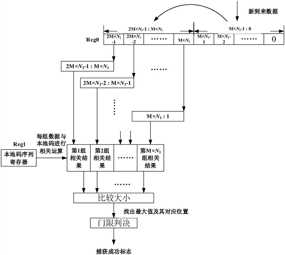
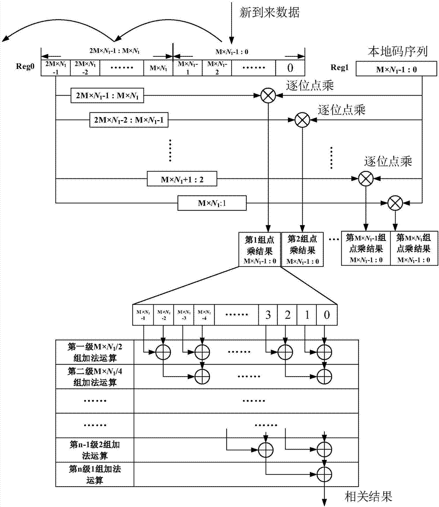
[0035] The structure of the high-speed receiver proposed by the present invention is as follows: figure 1 shown. A high-speed receiver in an integrated laser communication and ranging system, including an analog-to-digital converter (ADC): converting the received analog signal into a digital signal; a gigabit transceiver (GTH): serializing the digital signal of the ADC and conversion; Synchronization device: perform parallel data frame capture, dynamic correction and high-speed phase-locked loop tracking on the parallel signal output by GTH to complete signal synchronization; distance measurement branch: realize distance measurement through the synchronization signal obtained by the synchronization device; and communication support Road: through the synchronization signal obtained by the synchronization device to realize the communication dat...


PUM


Abstract

The present invention provides a synchronizer of a laser communication distance measurement integration system, a synchronization method of a laser communication distance measurement integration system and a high-speed receiver by using the synchronizer. The high-speed receiver receives high-speed signals, an analog-digital converter (ADC) is used for sampling of the high-speed signals, the sampling data is sent into a Gigabit transceiver (GTH) to perform serial-parallel conversion, and the high-speed serial data is converted to multi-path parallel data with low rate; the parallel data is sent into the synchronizer for signal synchronization, the parallel data is subjected to steps such as parallel data frame capture, dynamic correction, high-speed phase-locked loop tracking and the like in the synchronizer so as to complete accurate synchronization of the high-speed signals through the receiver; and moreover, on the basis of the accurate synchronization of the signals, and a distance measurement result and communication data can be solved out through the distance measurement branch and the communication branch of the receiver. The clock load is reduced and the complexity of the hardware realization is effectively reduced while ensuring the accurate synchronization of signals and accurate distance measurement and communication result.

Description

technical field [0001] The invention relates to a synchronizing device, a synchronizing method and a high-speed receiver using the synchronizing device in an integrated laser communication ranging system, belonging to the technical fields of electronic communication and radar. Background technique [0002] The integrated system of laser communication and ranging requires the use of lasers between space-based terminals (satellites) and ground stations, and between space-based terminals (satellites) and space-based terminals (satellites) to realize the integrated functions of high-speed data transmission and high-precision ranging. That is to use the same channel signal to simultaneously complete the two functions of communication and ranging. It is necessary to start with the similarities and differences of the two functions, and combine the calculation steps of the two as much as possible to save resources and power consumption and construct an intensive system. [0003] One...

Claims


Application Information

Patent Timeline
Patent Type & Authority Applications(China)
IPC IPC(8): H04L7/00
CPCH04L7/0016H04L7/007H04L7/0079H04L7/0087
Inventor 朱理辰卜祥元马永锋王继超
Owner BEIJING INSTITUTE OF TECHNOLOGYGY
Why Eureka
Eureka Blog
Learn More