
Single-crystal bar disconnection cutting equipment

A technology of cutting equipment and single crystal ingot, which is applied in the direction of metal processing equipment, stone processing equipment, grinding/polishing equipment, etc., can solve the problems of long time-consuming replacement of cutting wire, complicated wire-feeding mechanism, and large impact on precision, etc. Easy disconnection, low labor intensity and high degree of automation

Pending Publication Date: 2017-12-08
福州天瑞线锯科技有限公司
View PDF9 Cites 14 Cited by
  • Summary
  • Abstract
  • Description
  • Claims
  • Application Information

AI Technical Summary

Problems solved by technology

[0004] 1. Use a high-speed reciprocating long diamond wire to process and grind the silicon anchor through the wire feeding mechanism of the equipment; the cutting wire not only needs to be retracted and unwound, but also needs to be arranged according to a certain pitch. The elongation of the cutting wire is compensated by the tension device to prevent wire breakage. The wire feeding mechanism is complicated, and the wire is easy to break. If any part breaks, the entire long wire will be scrapped, resulting in waste, and the wire breakage during the cutting process will have a great impact on the accuracy. Replace the cutting machine. wire consumption time;

Method used


Image

  • Single-crystal bar disconnection cutting equipment
  • Single-crystal bar disconnection cutting equipment
  • Single-crystal bar disconnection cutting equipment

Examples


Embodiment Construction

[0026] The technical solution of the present invention will be further described below in conjunction with the accompanying drawings.

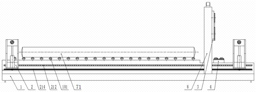
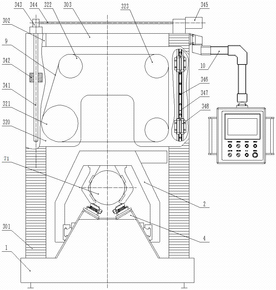
[0027] Such as Figure 1-7 As shown, a single crystal bar truncation and cutting equipment includes a frame, a single crystal bar feeding device that can slide on the bottom frame, a cutting frame installed on the bottom frame, and a wire installed on the cutting frame A sawing mechanism, a single crystal bar support device that can slide on the bottom frame, a feeding robot and a material truck, the bottom frame includes a base 1, and several support roller assemblies 101 on a fixed base, and the support roller assemblies are located on the cutting frame The left side of the base is installed on the "V"-shaped table of the base 1, and each two are symmetrically fixed in a group to form a support angle. The single crystal bar is placed on the support mechanism; the linear guide A212 and the rack A214, rack A214 cooperates with the gear in the...


PUM


Abstract

The invention discloses single-crystal bar disconnection cutting equipment. The single-crystal bar disconnection cutting equipment comprises a machine frame, a single-crystal bar feeding device, a cutting machine frame, a wire saw cutting mechanism, a single-crystal bar jacking device, a material collecting and conveying robot and a skip car, wherein the single-crystal bar feeding device can slide on an undercarriage for operation; the cutting machine frame is installed on the undercarriage; the wire saw cutting mechanism is installed on the cutting machine frame; and the single-crystal bar jacking device, the material collecting and conveying robot and the skip car can slide on the undercarriage. The single-crystal bar disconnection cutting equipment is characterized in that supporting roller assemblies are fixed to a base; clamping jaws of two movable clamping units are located above supporting rollers, and the clamping units can penetrate through the space below the cutting machine frame; the wire saw cutting mechanism achieves single-section cutting; servo motors drive speed reducers to drive gears to be engaged with racks so that a bar flotation jacking device can move; and the material collecting robot is located on the side face of the bar flotation jacking device. The single-crystal bar disconnection cutting equipment has the advantages that the clamping units and the single-crystal bar jacking device can be driven to move automatically through matching of the motors, the gears and the racks, the labor intensity of operators is low and the degree of automation is high; and diamond wires can be replaced conveniently, wire breaking cannot happen easily and the failure rate is low.

Description

technical field [0001] The invention belongs to the technical field of cutting hard and brittle materials, in particular to a diamond wire saw cutting device. Background technique [0002] In the Chinese patent literature, the name of the publication number CN201620055181.2 is a monocrystalline silicon cutting machine (see the specific implementation section of the application specification), which discloses a diamond wire that uses a high-speed reciprocating operation to pass through the wire-feeding mechanism of the equipment. It is a single crystal silicon cutting machine that processes and grinds silicon anchors, and finally realizes cutting and segmentation. [0003] shortcoming: [0004] 1. Use a high-speed reciprocating long diamond wire to process and grind the silicon anchor through the wire feeding mechanism of the equipment; the cutting wire not only needs to be retracted and unwound, but also needs to be arranged according to a certain pitch. The elongation of ...

Claims


Application Information

Patent Timeline
IPC IPC(8): B28D5/04B28D7/00B28D7/04B24B27/06
CPCB24B27/0633B28D5/0058B28D5/0082B28D5/045
Inventor 朱文志黄其勋李波林冬黄田玉林孝狮
Owner 福州天瑞线锯科技有限公司
Learn More