
Filament positioning system and filament positioning method

A positioning system and positioning method technology, applied in image data processing, instruments, discharge tubes, etc., can solve the problems of low efficiency, waste of resources, dim filament brightness, etc., to reduce labor time and labor intensity, reduce labor intensity and Labor time, accurate filament positioning effect

Active Publication Date: 2017-12-08
THE NAT CENT FOR NANOSCI & TECH NCNST OF CHINA
View PDF5 Cites 2 Cited by
  • Summary
  • Abstract
  • Description
  • Claims
  • Application Information

AI Technical Summary

Problems solved by technology

If the position of the filament is shifted, it is easy to cause the brightness of the filament to be dim, and the operator needs to increase the brightness by increasing the bias voltage or current, which will cause damage to the filament
At present, the replacement of the filament is completely manual, which not only wastes a lot of time of the instrument management personnel, but also when adjusting, because the tip of the filament and the center of the grid cap hole are not on the same plane, the difference in artificial vision may cause the deviation of the installation position of the filament, which will be different in different Affects the quality of microscope imaging to a certain extent
At the same time, due to differences in manufacturers and filament types, different electron microscope filaments have different filament positioning seats and filament bases. When positioning different types of filaments, different fixed installation modules are required to install and adjust the filaments, which is time-consuming. It is laborious and inefficient. While causing waste of resources, it is also difficult to ensure the accuracy of positioning

Method used


Image

  • Filament positioning system and filament positioning method
  • Filament positioning system and filament positioning method

Examples


Embodiment 1

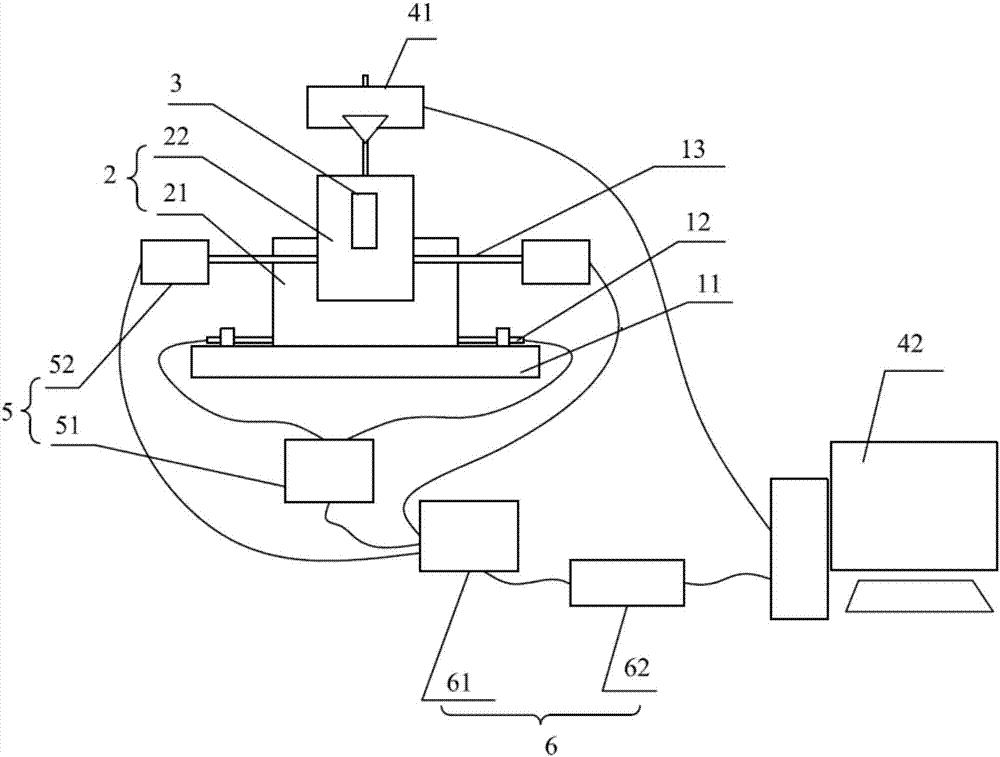
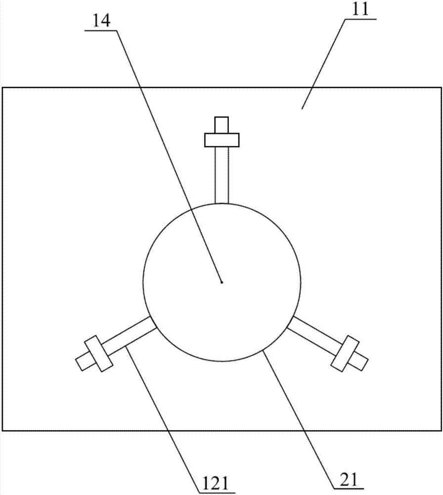
[0070] Such as figure 1 and 2 As shown, Embodiment 1 of the present invention provides a filament positioning system, including a bottom plate 11 , a first positioning adjustment mechanism 12 , a second positioning adjustment mechanism 13 , a detection module, a driving assembly 5 and a control assembly 6 . The bottom plate 11 is used to fix the first positioning adjustment mechanism and the filament seat 2; the first positioning adjustment mechanism 12 is used to position and fix different types of filament seats 2, and the second adjustment mechanism 13 is used to adjust the positioning of different types of filaments 3 , so that this filament positioning system is suitable for the positioning of different types of filaments 3; the detection module is used to detect the parameters required for adjusting the filament 3 and the filament holder 2; the drive assembly 5 is used to drive the first positioning adjustment mechanism 12 and the second positioning The adjustment mecha...

Embodiment 2

[0085] Embodiment 2 of the present invention provides a filament positioning method, which realizes the positioning of the filament 3 through manual adjustment, including the following steps:

[0086] Step 1: install the filament holder 2 and the filament 3 on the bottom plate 11 and the filament holder 2 respectively;

[0087] For the selected filament 3 that needs to be replaced, select a suitable filament holder 2 according to the type of the filament 3 . The filament holder 2 includes a filament positioning seat 22 and a filament base 21 that come with the electron microscope. The filament 3 is mounted on the filament positioning seat 22 through four connecting screws, the filament positioning seat 22 is mounted on the filament base 21 , and the filament base 21 is placed on the bottom plate 11 .

[0088] Step 2: The detection module displays the position information of the filament holder 2 and the filament 3;

[0089] The detection module may include an image acquisitio...

Embodiment 3

[0096] Embodiment 3 of the present invention provides a filament positioning method. The positioning of the filament 3 is realized in a semi-automatic manner. The steps are roughly the same as in Embodiment 2. The difference from Embodiment 2 is that the first positioning is driven by the drive assembly in steps 3 and 4. The adjustment mechanism and / or the second positioning adjustment mechanism work, specifically:

[0097]Step 3: Manually drive the driving assembly 5, so that the driving assembly 5 drives the first positioning adjustment mechanism 12 to adjust the position of the filament holder 2, so that the axis of the filament holder 2 passes through the second positioning center 14;

[0098] According to the pressure value of each pressure sensor in the position information, manually drive the first driving assembly 51, specifically, drive the first motor, so that the first motor drives each positioning rod 121 to move simultaneously, when each pressure value is greater t...


PUM


Abstract

The invention discloses a filament positioning system and a filament positioning method. The system and the method are used to solve problems that existing filament positioning efficiency is low and precision is low. The filament positioning system comprises a base plate, a first positioning adjusting mechanism and a second positioning adjusting mechanism. The first positioning adjusting mechanism is used for adjusting and positioning a position of a filament seat on the base plate so that the filament seats with different models can be fixed to the base plate. The second positioning adjusting mechanism is used for positioning and adjusting a filament. A detection module is used for collecting and displaying position information of a filament tip and the filament seat. The first positioning adjusting mechanism and the second positioning adjusting mechanism correspondingly adjust positions of the filament seat and the filament tip according to the position information. By using the filament positioning system and the filament positioning method adopting the filament positioning system, the system and the method are suitable for filament positioning of different types, and simultaneously traditional filament positioning precision and efficiency are increased.

Description

technical field [0001] The invention relates to the fields of mechanical engineering and automation, in particular to a filament positioning system and a filament positioning method. Background technique [0002] Electron microscopes, as a powerful tool for microscopic morphology observation, are being more and more rapidly and widely used in metallurgy, minerals, chemicals, medicine, biology, biomedicine, food, nanomaterials and other fields. Electron microscopes mainly include transmission electron microscopes and scanning electron microscopes. Transmission electron microscope (TEM) uses a focused electron beam as an illumination source, uses a thin film sample that is transparent to the electron beam, and uses the image formed by the transmitted electron beam or diffracted electron beam through the sample to analyze the microstructure inside the sample . The scanning electron microscope uses the high-energy electron beam reflected by the secondary electron to scan on th...

Claims


Application Information

Patent Timeline
Patent Type & Authority Applications(China)
IPC IPC(8): H01J9/18
CPCH01J9/18H01J37/067G06T7/73H01J37/244
Inventor 胡西学甘雅玲郭宏博徐晓慧王东亮
Owner THE NAT CENT FOR NANOSCI & TECH NCNST OF CHINA
Learn More