Cavity applying steam oven and steam oven

A steam oven and cavity technology, applied in the application, roaster/barbecue grid, kitchen utensils, etc., can solve the problems of shortening the service life of the steam oven, extremely high rust prevention requirements, complex processing procedures, etc., and achieve post-processing and manufacturing. Cost reduction, the effect of solving yellowing and high temperature resistance, and avoiding structure loosening or falling off

A steam oven and cavity technology, applied in the application, roaster/barbecue grid, kitchen utensils, etc., can solve the problems of shortening the service life of the steam oven, extremely high rust prevention requirements, complex processing procedures, etc., and achieve post-processing and manufacturing. Cost reduction, the effect of solving yellowing and high temperature resistance, and avoiding structure loosening or falling off

CN107485304AInactive Publication Date: 2017-12-19广东天倬智能家居有限公司

Image

  • Cavity applying steam oven and steam oven
  • Cavity applying steam oven and steam oven
  • Cavity applying steam oven and steam oven

Examples


Embodiment 1

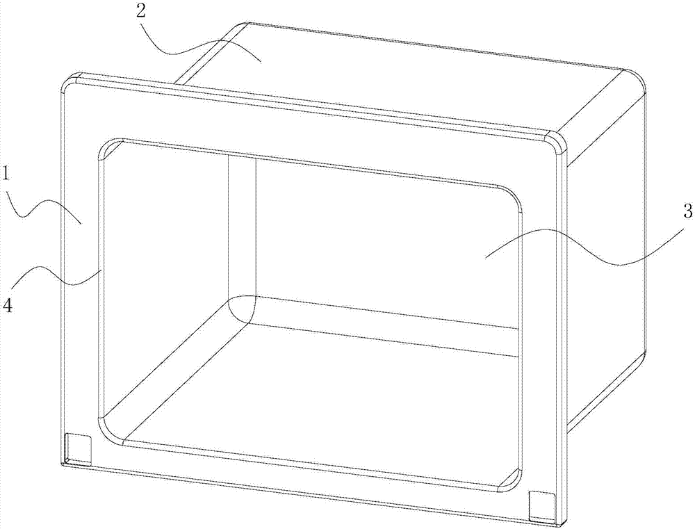
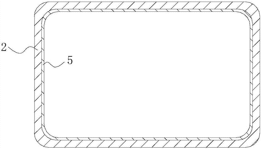
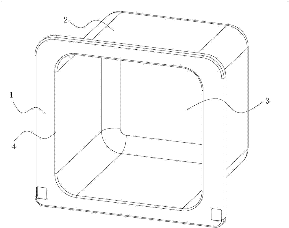
[0040] On the one hand, provide a cavity applied to a steam oven, such as figure 1 As shown, the cavity is made of metal integral stretch forming, and the cavity includes a front mounting plate 1, a U-shaped frame 2 and a rear plate 3, and the cavity is formed by combining the front mounting plate 1, the U-shaped frame 2 and the back plate 3 are made by one-shot stretch molding, such as figure 2 As shown, the inner surface of the cavity after integral stretching is coated with inorganic glass material 5, and the metal matrix of the cavity and the inorganic glass material 5 are coated and adhered by enamel process.

[0041]In this embodiment, the front mounting plate 1 is arranged at one end of the U-shaped frame 2 , and the rear plate 3 is arranged at the other end of the U-shaped frame 2 . The U-shaped frame 2 is an annular thin-walled structure with a through hole in the middle, and the rear plate 3 is arranged at one end of the U-shaped frame 2 and seals one end of the th...

Embodiment 2

[0046] The difference between this embodiment and Embodiment 1 is:

[0047] The outer surface of the cavity after integral stretching is also provided with inorganic vitreous material, and the metal matrix of the cavity is connected with the inorganic vitreous material through enamel process. The inorganic vitreous material is enamel. By arranging inorganic vitreous materials on the inner and outer surfaces of the cavity, the entire surface of the cavity can be protected, and any part of the cavity can be prevented from rusting in all aspects. The coastal area is especially important, which can effectively extend the service life of the product.

Embodiment 3

[0049] The difference between this embodiment and Embodiment 1 is:

[0050] Such as Figure 6 and 7 As shown, the inner heat shield 6 is provided on the rear plate 3 of the cavity, and the inner heat shield 6 is integrally formed with the rear plate 3 through deep drawing process, and the inner heat shield 6 Inorganic vitreous material is arranged on it. In this embodiment, the inner heat shield 6 is a groove structure recessed toward the inside of the cavity along the rear plate 3 , for providing installation space for the rear heating pipe and the convection fan.


PUM


Abstract

The invention discloses a cavity applying a steam oven. The cavity is formed by stretching and forming whole metal. The cavity comprises a front installation plate, a U-shaped frame and a rear plate, the cavity is formed by stretching and forming the front installation plate, the U-shaped frame and the rear plate at a time, the inner surface of the cavity formed by integrated stretching and forming is coated with an inorganic glassy material, and a metallic matrix of the cavity and the inorganic glassy material are used for coating and sticking through an enameling technology. The invention further provides the steam oven with the cavity. The cavity obtained by integrated stretching and forming is low in mold cost, no splicing gap exists, the consumption of sealing silica gel can be lowered, the sealing performance is good, the surface of the cavity can be completely covered with the inorganic glassy material, the rusting problem is eliminated, an enameled pressed steel plate is adopted for replacing expensive 304 stainless steel, the whole oven cost can be lowered, meanwhile the problems of yellowing and not resisting high temperature can be solved, the 400 DEG C or more high-temperature self-cleaning function can be achieved, and the problem that an existing steam oven is hard to clean is solved.

Description

technical field [0001] The invention relates to the technical field of household appliances, in particular to a cavity applied to a steam oven and the steam oven. Background technique [0002] An oven is an electrical product that uses electric heating elements to heat and bake food materials in a relatively closed cavity. A steam oven is based on an oven. In addition to the original heating elements, a steam generation system is added. Under the control of the control program, it realizes pure steaming, pure roasting, high-temperature steam heating, hot air circulation baking, and superposition and composite heating of various heating modes, and then becomes a new multifunctional all-in-one machine for cooking food. [0003] When a steam oven is working, its cavity should be completely sealed. The current technical solution is to use stainless steel to stamp and form, and the U-shaped frame, rear plate, and front mounting plate of the single-formed stamping parts are rivete...

Claims


Application Information

Patent Timeline
19 Dec 2017
Publication
CN107485304A
IPC
A47J37/06; A47J27/04; A47J36/00; A47J36/04; A47J36/02
CPC
A47J27/04; A47J36/00; A47J36/027; A47J36/04; A47J37/0629; A47J37/0664; A47J2027/043
Inventors
陶锐; 方锦鸿