Microfluidic chip apparatus for multi-channel simultaneous detection of six typical tumor markers

A microfluidic chip and tumor marker technology, which is applied in the field of microfluidic chip devices, can solve the problems of difficulty in passing fine liquid flow, has not been properly solved, and large flow resistance.

Inactive Publication Date: 2017-12-19
李榕生
View PDF6 Cites 2 Cited by
  • Summary
  • Abstract
  • Description
  • Claims
  • Application Information

AI Technical Summary

Problems solved by technology

[0008] But it's not that simple
[0009] First, this polydimethylsiloxane material, which is referred to by the acronym PDMS, is itself a strongly hydrophobic material, and channels are built on this material. modification operation, then, after the overall assembly is completed, that is, after the cover is covered, because the inner surface of the channel in the structure occupies most of the inner surface of the liquid flow channel, then the inner surface of the PDMS channel is The strong hydrophobicity is the decisive factor, it will make it very difficult for the polar liquid fine flow similar to the aqueous solution to pass through, and its flow resistance is so large that even the general micropump is difficult to push, of course, if the cover sheet is also If you choose to use the PDMS material, then the problems are basically the same, with minor differences; therefore, in the prior art, it is necessary to modify and modify the inner surface of the channel on the PDMS material; then, this is for the PDMS channel Is the modification operation of the inner surface of the channel very troublesome? That's not the problem. What constitutes a serious technical problem is an

Method used


Image

  • Microfluidic chip apparatus for multi-channel simultaneous detection of six typical tumor markers

Examples


Embodiment Construction

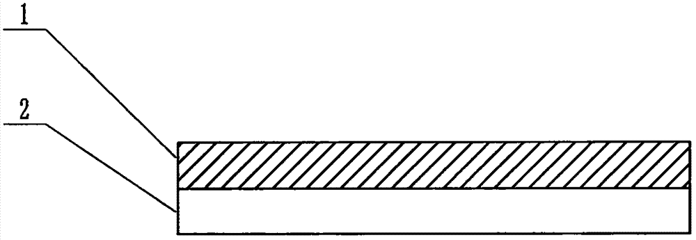
[0070] in figure 1 In the example shown in the present case, the feature of this example is that the structure of the device includes a multi-channel microfluidic chip, and the structure of the microfluidic chip includes a substrate 1 and a cover sheet 2 that are attached to each other. The substrate 1 and the cover sheet 2 are both plate-like or sheet-like objects, and the surface of the substrate 1 facing the cover sheet 2 contains a channel structure formed by a molding process or an etching process. 1 It also contains a window structure that is connected to the channel structure and penetrates the substrate through a molding process, an etching process or a simple perforation process, and the substrate 1 and the cover sheet 2 that are attached to each other are constructed together A microfluidic chip containing a pipe structure and a liquid pool structure connected to it is formed. The pipe structure is located at the interface area where the substrate 1 and the cover shee...


PUM

PropertyMeasurementUnit
Particle sizeaaaaaaaaaa
Diameteraaaaaaaaaa
Lengthaaaaaaaaaa

Abstract

The present invention relates to a microfluidic chip apparatus for multi-channel simultaneous detection of six typical tumor markers, and belongs to the field of analytical testing. According to the present invention, the use of inexpensive and easily-processed polydimethylsiloxane (PDMS) to produce the substrate of a microfluidic chip for multi-channel simultaneous detection of six typical tumor markers has a series of problems that the surface of the PDMS is strongly hydrophobic and the surface chemical modification effect is difficult to last. The technical scheme of the present invention is that the substrate material is PDMS with an original ecological surface, the pipeline of the chip is filled with doped micron-scale titanium dioxide particles, the surface super-hydrophilicity of the titanium dioxide particles can be induced by visible light irradiation in advance, and the set of the titanium dioxide particle filler and the super-hydrophilic gap between the particles can compensate and beyond the original strong hydrophobic pipeline, such that the constant and super hydrophilic modification effect is achieved. In addition, the titanium dioxide filler can further be used for preventing the pipeline of the chip from collapsing and deforming, and blocking biological macromolecules from contacting the inner wall of the pipeline.

Description

Technical field [0001] The invention relates to a microfluidic chip device for multi-channel simultaneous detection of six typical tumor markers, which belongs to the field of analysis and testing. Background technique [0002] Tumor marker (TM) refers to a class of substances that are produced by tumor cells themselves or by the body’s response to tumor cells during the occurrence and proliferation of tumors, and reflect the existence and growth of tumors, including Proteins, hormones, enzymes (isoenzymes) and oncogene products, etc. Testing the tumor markers in the blood or body fluid of the patient can detect the tumor early in the tumor screening, and observe the efficacy of tumor treatment and judge the prognosis of the patient. Currently commonly used clinical tumor markers are: (1) alpha-fetoprotein (AFP) is a marker for primary liver cancer, testicular cancer, ovarian cancer and other tumors; (2) carcinoembryonic antigen (CEA) is a tumor of the digestive system, Markers...

Claims


Application Information

Patent Timeline
IPC IPC(8): B01L3/00G01N33/574G01N27/327G01N27/26
CPCB01L3/5027B01L2200/027B01L2200/10B01L2300/0861G01N27/26G01N27/3275G01N33/57484
Inventor 李榕生
Owner 李榕生
Why Eureka
Try Eureka