
Ice making mechanism on ice making machine

An ice machine and ice chamber technology, applied in ice making, ice making, ice storage/distribution, etc., can solve problems such as low efficiency and slow ice making speed, reduce heat loss, reduce energy consumption, and shorten flow rate The effect of track length

Inactive Publication Date: 2017-12-22
浦江县酉泽水产科技有限公司
View PDF5 Cites 1 Cited by
  • Summary
  • Abstract
  • Description
  • Claims
  • Application Information

AI Technical Summary

Problems solved by technology

Most of the existing ice machines put water in the ice box, and set a plurality of small compartments in the ice box. After the water condenses into ice, ice cubes will be formed in each small compartment. This refrigeration method uses Cold air cools the water, making ice slower and less efficient

Method used


Image

  • Ice making mechanism on ice making machine
  • Ice making mechanism on ice making machine
  • Ice making mechanism on ice making machine

Examples


Embodiment 1

[0020] like Figure 1~4 as shown,

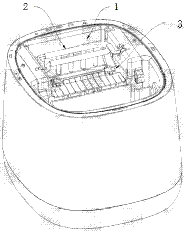
[0021] An ice-making mechanism on an ice-making machine includes a compressor 3 and an evaporator 2 connected to the compressor, and the evaporator is arranged in an ice-making chamber 1 of the ice-making machine.

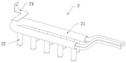
[0022] The evaporator includes a U-shaped pipe 21 placed horizontally; the lower end of the U-shaped pipe protrudes downward to form a plurality of branch pipes; the upper end of the branch pipe 22 is connected with the U-shaped pipe, the lower end of the branch pipe is closed, and the branch pipe extends into the water in the ice chamber. A two-way electromagnetic valve is arranged between the high-pressure steam outlet of the compressor 3 and the steamer. When the compressor 3 works, the evaporator 2 cools down, ice condenses around the branch pipe 22, then the two-way solenoid valve works, the high-pressure steam output by the compressor 3 is transmitted to the evaporator, the evaporator heats up, and the ice cubes on the bra...

Embodiment 2

[0028] like Figure 1~4 As shown, when the compressor 3 works, the evaporator 2 cools down, and ice condenses around the branch pipe 22, and then the two-way solenoid valve works, and the high-pressure steam output by the compressor 3 is transmitted to the evaporator 2, and the evaporator 2 heats up, and the branch pipe 22 The ice cubes fell off. The water is directly in contact with the evaporator 2, and the ice-forming speed is fast, and ice cubes can be produced when it is refrigerated. The ice-shoveling mechanism arranged under the evaporator sends the generated ice cubes out of the ice-making chamber 1 .

[0029] The inner wall of the ice-making chamber 1 is coated with an anti-freezing and sticking coating, and the coating is composed of components A and B: the components of component A and their parts by weight are: 70-110 parts of vinyl-terminated polysiloxane, ethylene 25~45 parts of trifluoropropylpolysiloxane, 18~26 parts of silica nanoparticles, 20~30 parts of or...


PUM

PropertyMeasurementUnit
angleaaaaaaaaaa

Abstract

The invention discloses an ice making mechanism on an ice making machine. The ice making mechanism comprises a compressor and an evaporator connected with the compressor, and the evaporator is arranged in an ice making cavity of the ice making machine. The ice making mechanism has the beneficial effects that when the compressor works, the evaporator is cooled, ice is formed around branch pipes in a congealed manner, then a two-way solenoid valve works, high pressure steam output by the compressor is transmitted to the evaporator, the evaporator is heated, and ice blocks on the branch pipes fall. Water is directly in contact with the evaporator, the ice forming speed is high, and the ice blocks can be generated during refrigeration. The made ice blocks can be directly used, crushing and machining again are not needed; and in addition, by means of the above design, the distance between the two branch pipes can be minimum, the runner length of the evaporator is decreased, the heat exchange length is further decreased, and heat losses are reduced.

Description

technical field [0001] The invention relates to the technical field of ice making, in particular to an ice making mechanism on an ice making machine. Background technique [0002] An ice machine is a refrigeration mechanical device that generates ice after water is cooled by the refrigerant of the refrigeration system through an evaporator. Most of the existing ice machines put water in the ice box, and set a plurality of small compartments in the ice box. After the water condenses into ice, ice cubes will be formed in each small compartment. This refrigeration method uses The cold air cools the water, making ice slower and less efficient. Contents of the invention [0003] The object of the present invention is to provide an ice making mechanism with fast ice making speed, high ice making efficiency, fast ice output speed, and no ice layer sticking to the ice making machine in the ice making chamber. [0004] Aiming at the problems mentioned in the background technology...

Claims


Application Information

Patent Timeline
Patent Type & Authority Applications(China)
IPC IPC(8): F25C1/12F25C5/04C09D183/07C09D183/08C09D7/12
CPCF25C1/12C08K2201/011C08L2205/025C08L2205/035C09D183/04F25C5/043C08L83/08C08K3/36
Inventor 孙弋博
Owner 浦江县酉泽水产科技有限公司
Learn More