
Adjustment method for lens group

An assembling method and mirror group technology, which are applied in the field of optical interferometry, can solve problems such as systematic errors and the influence of measurement results, and achieve the effects of improving accuracy, saving computing time, and simplifying the amount of calculation.

Active Publication Date: 2017-12-22
NANJING UNIV OF SCI & TECH
View PDF9 Cites 10 Cited by
  • Summary
  • Abstract
  • Description
  • Claims
  • Application Information

AI Technical Summary

Problems solved by technology

[0004] However, in the non-zero position interference system, the adjustment error will lead to a large system error, and the system error will have a great impact on the measurement results. General machining cannot guarantee that the position of each lens in the system meets the design requirements.

Method used


Image

  • Adjustment method for lens group
  • Adjustment method for lens group
  • Adjustment method for lens group

Examples


Embodiment 1

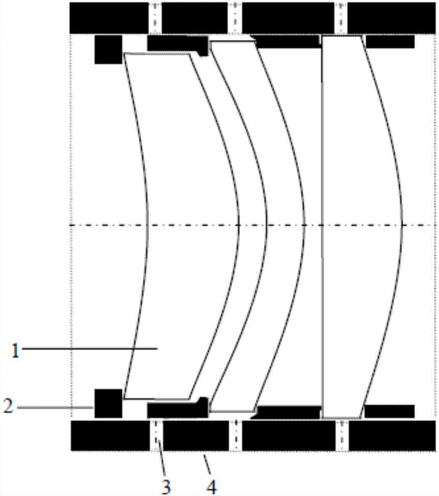
[0028] First, according to the designed lens, the mechanical structure of the lens barrel is designed, such as figure 2 In the collimator lens barrel shown, a spacer 2 is used to ensure the distance between each lens 1, and high-precision machining ensures that the tilt and pitch are infinitely close to zero, and the position of each lens 1 will have a symmetrical position The four adjustment screws 3 are screwed into the straight thread against the lens 1. In the center deviation measuring instrument, the center position of the lens 1 can be adjusted by changing how much each adjustment screw 3 is screwed in, and the center of the lens 1 is aligned with the whole After the optical axes of the lens barrels 4 coincide, the adjusting screws 3 are tightened, so that each lens 1 can be fixed in the lens barrel 4 . The specific process is as follows:


PUM


Abstract

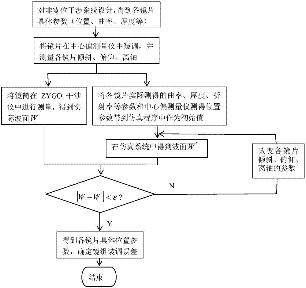
The invention discloses an adjustment method for a lens group. The method comprises the following steps: setting the size of a lens cone according to the parameters of the lens group, and enabling a lens cone wall corresponding to each lens to be uniformly provided with four adjustment screws in a peripheral direction; employing a lever indicator to adjust the position of the lens cone and the position of a decentration measurement instrument during adjustment, and adjusting the horizontal position and pitching position of a workbench and the optical axis of a central laser light beam; adjusting the optical axis of the first lens through the adjustment screws, employing a separation ring for fixing, and then placing the lever indicator into the next lens for the adjustment of the optical axis; recording the actual adjustment error of each lens; substituting the parameters of each lens into a simulation system, and obtaining an ideal simulation wave surface of the lens group; measuring the adjusted lens cone, and obtaining an actual wave surface; comparing the ideal simulation wave surface with the actual wave surface, wherein the difference between the ideal simulation wave surface obtained through new simulation and the actual wave surface is less than a threshold value, thereby obtaining the adjustment error of the lens group. The method is high in error calibration precision, and greatly improves the measurement precision of the whole optical system.

Description

technical field [0001] The invention relates to the technical field of optical interference measurement, in particular to an assembly and adjustment method of a mirror group. Background technique [0002] Modern high-performance optoelectronic systems, such as large-scale astronomical telescopes, large-scale augmented reality (AR), large-scale virtual reality (VR), and space cameras, require a simple optical structure using only one imaging mirror to achieve high-performance optical quality. Free-form optical elements can correct almost all aberrations by using their own high-order changes in curvature, while simplifying the system structure [5-8] , is an ideal component of modern high-performance optoelectronic systems. However, the large aperture and large degree of freedom of this type of component have brought many complex and difficult scientific problems to the high-precision measurement of its surface shape, and it is difficult to meet the quality of the imaging opti...

Claims


Application Information

Patent Timeline
Patent Type & Authority Applications(China)
IPC IPC(8): G02B7/02G02B27/62
CPCG02B7/021G02B7/023G02B7/026G02B27/62
Inventor 沈华王劲松李嘉朱日宏高金铭矫岢蓉孙越陈磊
Owner NANJING UNIV OF SCI & TECH
Learn More