
Low-temperature co-fired microwave dielectric ceramic material and preparation method thereof

A microwave dielectric ceramic and low-temperature co-firing technology is applied in the field of microwave dielectric materials and their manufacturing methods, and can solve problems such as affecting the characteristics of original materials, inability to use multilayer capacitor components, and difficult processing.

Active Publication Date: 2017-12-29
WALSIN TECHNOLOGY CORPORATION
View PDF5 Cites 24 Cited by
  • Summary
  • Abstract
  • Description
  • Claims
  • Application Information

AI Technical Summary

Problems solved by technology

However, although the above method can reduce the sintering temperature of the original ceramic material, because the properties of the added material and the raw material are different, it usually affects the properties of the original material (such as high-frequency dielectric properties), or makes subsequent processing difficult.
[0007] In addition, in addition to lowering the sintering temperature of glassy materials, microwave dielectric materials and glass materials must be made into slurry in the high-frequency multilayer capacitor assembly process. Polyvinyl alcohol (PVA) or polyvinyl alcohol (PVA) or polyvinyl alcohol (PVA) Vinyl butyral (PVB) as a binder, according to previous research reports [J.Am.Ceram.Soc., 93 3049-3051 (2010)], PVA or PVB and flux boron oxide (B 2 o 3 ) will produce a crosslinking reaction to form a three-dimensional (three dimentional; 3-D) network gel state structure, which will greatly increase the viscosity of the slurry, which is not conducive to the coating process and cannot be applied to the production of multilayer capacitor components.
[0008] However, how to take into account low-temperature sintering and maintain the superior electrical properties and machinability of ceramic materials has always been a difficult problem in material design.

Method used


Image

  • Low-temperature co-fired microwave dielectric ceramic material and preparation method thereof
  • Low-temperature co-fired microwave dielectric ceramic material and preparation method thereof
  • Low-temperature co-fired microwave dielectric ceramic material and preparation method thereof

Examples


Embodiment Construction

[0030] Specific examples will be described below to illustrate the implementation of the present invention, but they are not intended to limit the protection scope of the present invention.

[0031] The first embodiment of the present invention provides a low temperature co-fired microwave dielectric ceramic material, which includes: 85wt% to 99wt% ceramic material and 1wt% to 15wt% glass material. The dielectric constant of the above-mentioned microwave dielectric ceramic material ranges from 8 to 15, which belongs to the range of low dielectric constant, and microwave dielectric materials with high quality factor and temperature frequency coefficient close to zero at the same time, and its sintered density distribution is 3.17 to 3.52g / cm 3 , quality factor distribution is 2900~6500, insulation resistance characteristics≧3.5×10 12 Ω.

[0032] The ceramic material is 1-y-z[(1-x)Mg 2 SiO 4 -xCa 2 SiO 4 ]-yCaTiO 3 -zCaZrO 3 . According to research, (1-x)Mg 2 SiO 4 -...


PUM

PropertyMeasurementUnit
Sintered densityaaaaaaaaaa
Temperature coefficientaaaaaaaaaa

Abstract

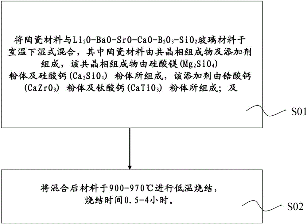
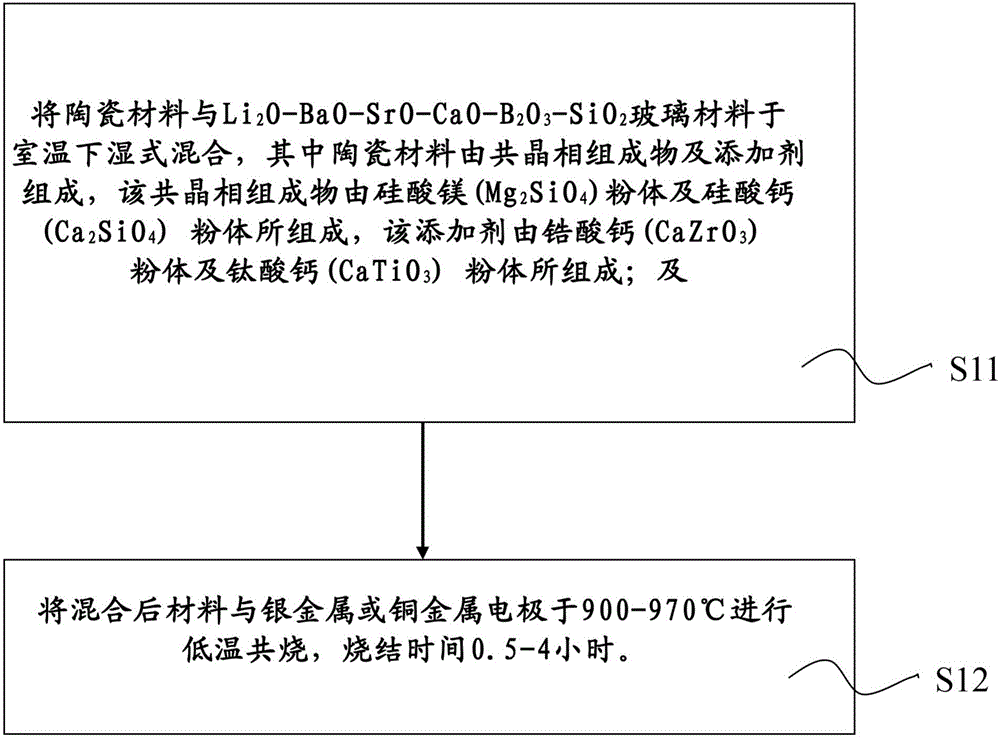
The invention provides a microwave dielectric ceramic material which can be cofired with a silver or copper electrode at a low temperature and a preparation method thereof. The microwave dielectric ceramic material is prepared from a microwave dielectric ceramic material 1-y-z[(1-x)Mg2SiO4-xCa2SiO4]-yCaTiO3-zCaZrO3, and mixed with a multicomponent glass material Li2O-BaO-SrO-CaO-B2O3-SiO2, wherein x is more than or equal to 0.2 and is less than or equal to 0.7, y is more than or equal to 0.05 and is less than or equal to 0.3, and z is more than or equal to 0.02 and is less than or equal to 0.15. The low-temperature co-fired microwave dielectric ceramic material can be co-fired with silver or copper and other conductive metals at 900-970 DEG C at an atmosphere and inert gas environment. The material has excellent characteristics of low dielectric consumption, high quality factor, low temperature capacitance and the like, and is applicable to multilayer ceramic component manufacture procedure and processing after being fired.

Description

technical field [0001] The invention relates to a microwave dielectric material and its preparation method, in particular to the microwave dielectric material produced by low temperature co-fired ceramic technology. Background technique [0002] With the needs and development of the current communication industry, in order to meet the multi-functional and thin, light and small requirements of wireless communication modules, the miniaturization and modularization of radio frequency circuits has become the focus of research and development in today's industry. The size of microwave components and the spacing between wires are constantly shrinking, so that when electronic signals are transmitted between metals, the resistance-capacitance value between metal wires increases, which increases power consumption and exchange interference between signals and causes signal delays ( RC slow). In addition, low temperature co-fired ceramic materials and process technology have been wide...

Claims


Application Information

Patent Timeline
IPC IPC(8): C04B35/20C04B35/22C04B35/622C04B35/64C03C3/089C03C3/064
CPCC03C3/064C03C3/089C04B35/20C04B35/22C04B35/622C04B35/64C04B2235/3232C04B2235/3244C04B2235/365C04B2235/407C04B2235/408
Inventor 朱立文梁志豪冯奎智
Owner WALSIN TECHNOLOGY CORPORATION
Learn More