Reconfigurable antenna and manufacturing method therefor

A technology for reconstructing antennas and antenna layers. It is applied in the directions of antennas, antenna grounding devices, and radiating element structures. It can solve the problems of small tuning range, large loss, and single reconfigurability. The effect of good polarization and frequency reconfigurability

Inactive Publication Date: 2018-01-05
UNIV OF ELECTRONICS SCI & TECH OF CHINA
View PDF2 Cites 3 Cited by
  • Summary
  • Abstract
  • Description
  • Claims
  • Application Information

AI Technical Summary

Problems solved by technology

[0003] The technical problem to be solved by the present invention is the technical problem of small tuning range, single reconfigurability, and large loss in the prior art. It provides a new reconfigurable antenna, which can simultaneously realize frequency reconfigurability and The polarization can be reconfigured, it has a large tuning range and good reconfigurable performance, and it also has the technical characteristics of small size and low loss

Method used


Image

  • Reconfigurable antenna and manufacturing method therefor
  • Reconfigurable antenna and manufacturing method therefor
  • Reconfigurable antenna and manufacturing method therefor

Examples


Embodiment 1

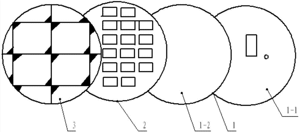
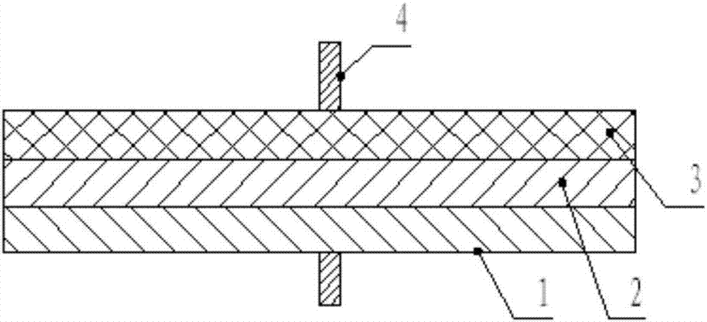
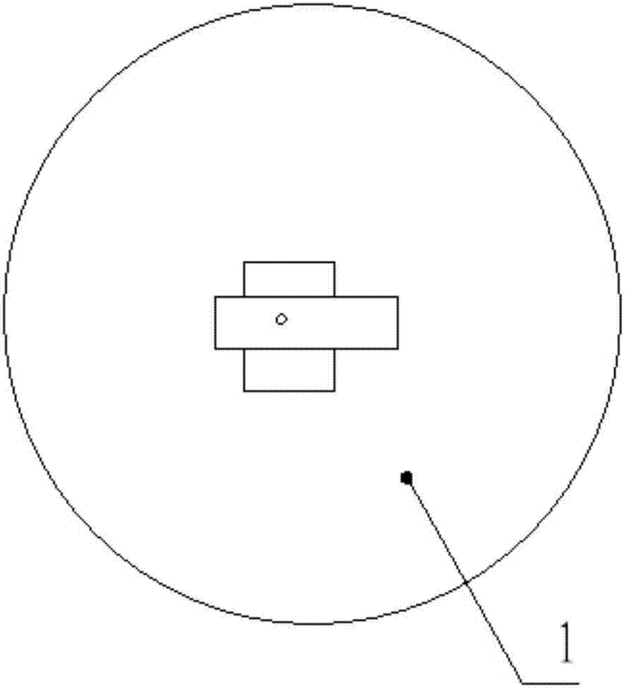
[0036] This embodiment provides a reconfigurable antenna, the specific structure is as follows Figure 1-5 As shown, it includes the source antenna layer with the same radius and the same thickness from bottom to top, the metal ring structure layer of the metasurface and the metal chamfer structure layer of the metasurface. The dielectric substrates of these three layers are all RO4350B, Its dielectric constant is 3.48, and the thickness h is 1.524mm; the center of the source antenna layer, the metal ring structure layer of the metasurface and the metal chamfer structure layer of the metasurface are on the same axis, and are fixed by metal rods at the center of the circle. The source antenna layer, the metal ring structure layer of the metasurface and the metal chamfer structure layer of the metasurface are compactly overlapped, and the reconfigurable antenna adopts the back feeding of the coaxial line; the source antenna layer adopts a slot microstrip antenna structure, includ...


PUM


Abstract

The invention relates to a reconfigurable antenna and a manufacturing method therefor, and mainly aims to solve the problems of small tuning range, single re-configurability and high loss of the reconfigurable antenna in the prior art. A technical scheme is adopted as follows: the reconfigurable antenna comprises a source antenna layer, a metal ring structural layer and a metal cut corner structural layer arranged from the bottom up; the source antenna layer adopts a slit microstrip antenna structure, and comprises a floor with rectangular coupling slits and a dielectric plate with rectangularmetal radiation patches; the metal ring structural layer comprises rectangular metal ring units periodically arranged in the directions of X axis and Y axis; the metal cut corner structural layer comprises square metal cut corner units periodically arranged in the directions of X axis and Y axis; the metal ring structural layer performs clockwise rotation to form an included angle <theta>1 with the X axis; and the metal cut corner structural layer performs clockwise rotation to form an included angle <theta>2 with the X axis. By virtue of the method, the problems are well solved, and the reconfigurable antenna can be used for an intelligent communication system.

Description

technical field [0001] The invention belongs to the technical field of antennas, in particular to a reconfigurable antenna related to polarization and frequency. Background technique [0002] In recent years, polarization reconfigurable antennas are especially suitable for mobile terminals with limited volume because they can add independent transmit and receive channels without increasing the antenna volume. At the same time, the multipath fading effect of radio signals has a serious impact on the communication quality of many wireless communication systems. The use of polarization reconfigurable antennas can not only eliminate multipath fading effects, but also increase frequency reuse, so polarization reconfigurable antennas It has become a hotspot in the research of reconfigurable antennas. Generally speaking, polarization reconfigurable antennas are mostly realized through electronic tuning technology. By increasing the low-frequency bias voltage and controlling the bi...

Claims


Application Information

Patent Timeline
Patent Type & Authority Applications(China)
IPC IPC(8): H01Q1/38H01Q1/48H01Q15/24H01Q19/00
Inventor 陈会万应禄石宪青朱磊
Owner UNIV OF ELECTRONICS SCI & TECH OF CHINA
Why Eureka
Try Eureka