Dry-process smoke denitration method

A flue gas and denitrification technology, applied in the field of dry flue gas denitrification, can solve the problems of increasing the operating cost of the denitration system, decomposing dust inactivation, reducing the denitrification efficiency, etc. Effect

Inactive Publication Date: 2018-01-09
ZHONGJING ENVIRONMENTAL TECH CO LTD
View PDF6 Cites 3 Cited by
  • Summary
  • Abstract
  • Description
  • Claims
  • Application Information

AI Technical Summary

Problems solved by technology

Although this oxidative denitrification method can achieve the purpose of removing nitrogen oxides, the O 3 In an environment with a smoke temperature exceeding 130°C and a dust content of 50-200mg/Nm 3 Under the flue gas c

Method used


Image

  • Dry-process smoke denitration method
  • Dry-process smoke denitration method
  • Dry-process smoke denitration method

Examples


Embodiment 1

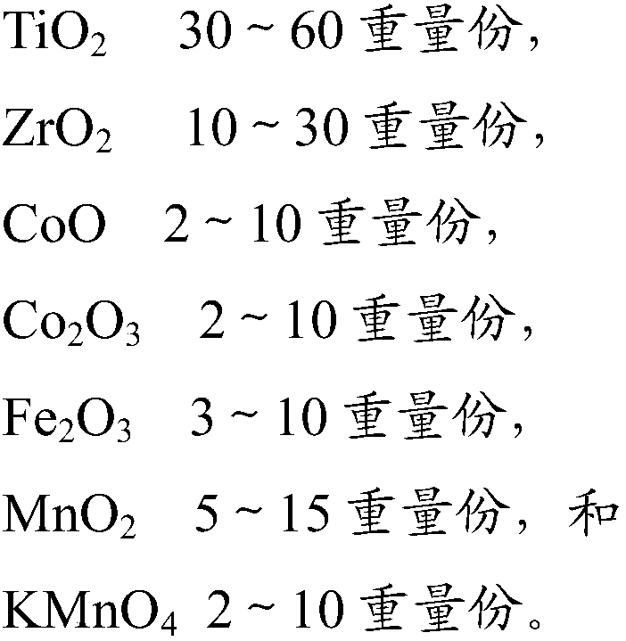
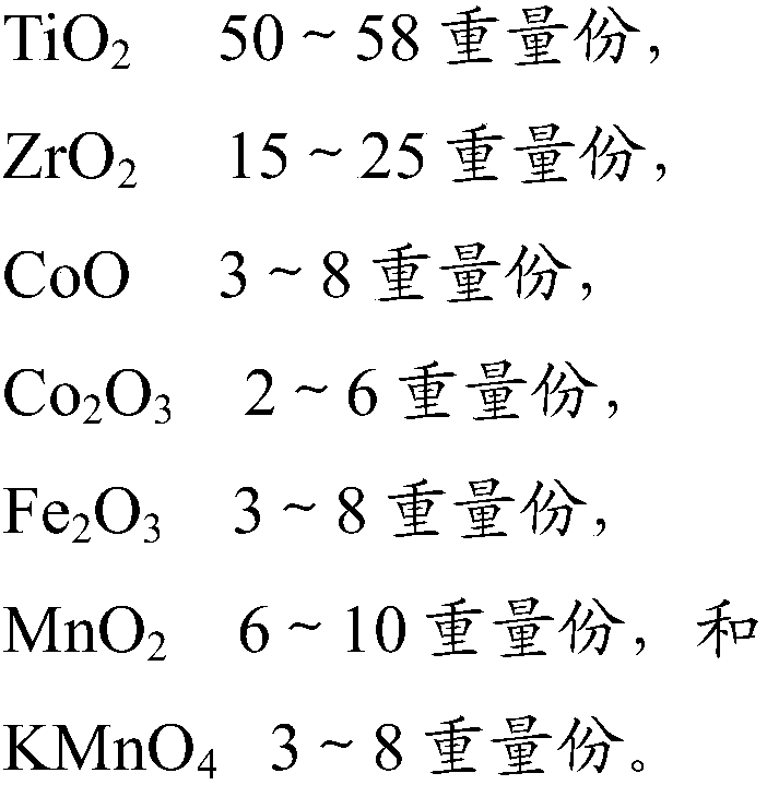
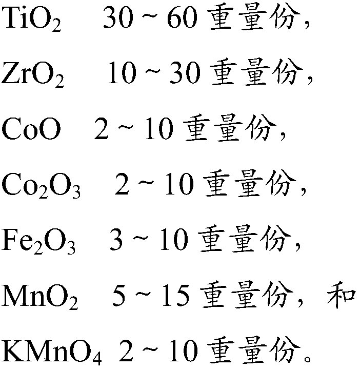
[0048] Will CoO, Co 2 o 3 , Fe 2 o 3 , MnO 2 and KMnO 4 As an active ingredient, TiO 2 and ZrO 2 As a carrier, the denitration catalyst B1 was obtained by impregnation method.

[0049] Table 1. Formula of denitrification catalyst B1

[0050] TiO 2

55.0 parts by mass

ZrO 2

20.0 parts by mass

CoO

5.0 parts by mass

co 2 o 3

5.0 parts by mass

Fe 2 o 3

3.0 parts by mass

MnO 2

7.0 parts by mass

KMnO 4

5.0 parts by weight

[0051] The flow velocity of the flue gas to be treated is 3.5m / s; other parameters of the flue gas inlet and parameters of the flue gas outlet are shown in Tables 2 and 3. The flue gas to be treated passes through the pre-dust collector to remove most of the dust particles in advance to obtain the flue gas to be denitrated, and the pre-dust removal efficiency is above 90%. The flue gas to be denitrated passes through the catalytic bed equipment, which inclu...

Embodiment 2

[0060] Adopt the formula of table 5 to obtain denitration catalyst B2, other conditions are identical with embodiment 1. Refer to Table 6 for flue gas outlet parameters. The concentration of nitrogen oxides in the clean flue gas is 42mg / Nm 3 , the denitrification efficiency is 92.51%.

[0061] Table 5. Formula of denitrification catalyst B2

[0062] TiO 2

53.0 parts by mass

ZrO 2

20.0 parts by mass

CoO

5.0 parts by mass

co 2 o 3

5.0 parts by mass

Fe 2 o 3

5.0 parts by mass

MnO 2

7.0 parts by mass

KMnO 4

5.0 parts by weight

[0063] Table 6. Flue gas outlet parameters

[0064] serial number

Embodiment 3

[0066] Adopt the formula of table 7 to obtain denitration catalyst B3, other conditions are identical with embodiment 1. Refer to Table 8 for flue gas outlet parameters. The concentration of nitrogen oxides in the clean flue gas is 38mg / Nm 3 , the denitrification efficiency is 93.32%.

[0067] Table 7. Formula of denitrification catalyst B3

[0068] TiO 2

51.0 parts by mass

ZrO 2

20.0 parts by mass

CoO

5.0 parts by mass

co 2 o 3

5.0 parts by mass

Fe 2 o 3

7.0 parts by mass

MnO 2

7.0 parts by mass

KMnO 4

5.0 parts by weight

[0069] Table 8. Flue gas outlet parameters

[0070] serial number


PUM


Abstract

The invention discloses a dry-process smoke denitration method. The method comprises the following steps: (1) a pre-dusting step, namely carrying out pre-dusting on smoke to be treated so as to removemost part of dust particles, thus forming smoke to be denitrated; (2) an oxidization step, namely oxidizing nitric oxide in the smoke to be denitrated into nitrogen dioxide in a catalyst bed device by adopting a denitration catalyst so as to form oxidized smoke, wherein the denitration smoke contains a carrier and an active ingredient, the carrier is nano-scale amphoteric oxide and is selected from one or more of TiO2, ZrO2 or HfO2, and the active ingredient includes CoO, Co2O3, Fe@O3, MnO2 and KMnO4; and (3) an absorption step, namely carrying out dry-process denitration on oxidized smoke inan absorption device by adopting a denitration agent taking magnesium oxide as the main ingredient, thus forming treated smoke. According to the method disclosed by the method, the denitration efficiency is high, the process flow is simple, the water consumption is few, and the investment and running cost are lower.

Description

technical field [0001] The invention relates to a method for dry flue gas denitrification, in particular to a catalyst-based dry flue gas denitrification method. Background technique [0002] In recent years, the problem of air pollution has become increasingly serious. With the increasing demand for energy, the pollution caused by flue gas emissions has become increasingly prominent, and the problem of air pollution control has attracted great attention from people all over the world. The development of efficient, energy-saving, and cost-effective flue gas purification methods can fundamentally solve the different demands of development and environmental protection, as well as current and long-term needs. [0003] As far as flue gas denitrification technology is concerned, at present, domestically, it is mainly aimed at low NOx in the combustion process. x Produced while extensively researched, through a variety of low NO x technology to design a variety of low NO x bur...

Claims


Application Information

Patent Timeline
IPC IPC(8): B01D53/75B01D53/86B01D53/81B01D53/56B01D53/96B01D46/02
Inventor 童裳慧
Owner ZHONGJING ENVIRONMENTAL TECH CO LTD
Why Eureka
Try Eureka