Novel micro ball end milling cutter and edge sharpening preparation technology
What is Al technical title?
Al technical title is built by PatSnap Al team. It summarizes the technical point description of the patent document.
A ball-end milling cutter and micro technology, applied in milling cutters, manufacturing tools, milling machine equipment, etc., can solve the problems of not meeting the requirements of the micro milling field, and achieve the effect of easy guarantee of geometric structure, simple structure and simple operation.
Active Publication Date: 2018-01-09
BEIJING INSTITUTE OF TECHNOLOGYGY
View PDF5 Cites 13 Cited by
Summary
Abstract
Description
Claims
Application Information
AI Technical Summary
This helps you quickly interpret patents by identifying the three key elements:
Problems solved by technology
Method used
Benefits of technology
Problems solved by technology
The design idea of most micro-milling cutters is to simplify the structure of traditional helical-edged milling tools, but in actual micro-milling, due to the existence of scale effects, traditional helical-edged micro-milling cutters show defects that have not been seen in traditional milling , can not meet the requirements of the field of micro-milling
Method used
Image
Click on the blue label to locate the original text in one second.
Reading with bidirectional positioning of images and text.
Examples
Embodiment Construction
[0017] The object of the present invention is to provide a new type of micro ball end milling cutter and its grinding preparation method, which is used to reduce the difficulty of preparing the micro ball end milling cutter, improve the cutting performance of the micro ball end milling cutter, and meet the application needs of micro milling processing.
[0018] Realize the technical scheme of the present invention as follows:
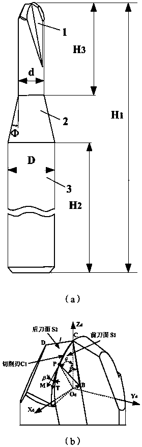
[0019] A new type of integral micro ball end milling cutter, its overall structure figure 1 As shown in (a), it is mainly composed of a ball head and a cylindrical cutter head part 1, a conical cutter neck part 2 and a cylindrical shank part 3. The total length of the micro ball end milling cutter is H1≤60mm, and the diameter of the ball head part d≤0.5mm, the length of the cutter head part is H 3 ≤3mm, the cone angle of the conical knife neck part is Ф=10°~30°, the diameter of the cylindrical knife handle part is D≤3.175mm, and the length is H 2 ≤20m...
PUM
Property
Measurement
Unit
length
aaaaa
aaaaa
Abstract
The invention discloses a novel micro ball end milling cutter and an edge sharpening preparation technology of the novel micro ball end milling cutter, and belongs to the technical field of micro milling machining. The overall structure of the milling cuter is mainly composed of a cutter head part composed of a ball end and a cylinder, a conical cutter neck part and a cylindrical cutter handle part. The structure of the ball end part is designed to be a center-symmetrical two-edge structure, the front cutter face is an inclined plane, the rear cutter face is a conical face, and a cutting edgeis formed by a curve formed by crossing the inclined plane and the conical face. By means of the design method, on one hand, the cutter cutting edge strength can be improved, contact friction betweenthe cutter and a workpiece is reduced, accordingly, cutter abrasion is effectively reduced, the cutter service life is prolonged, and the dynamic unbalance value of the cutter is reduced through the symmetrical structure design; and on the other hand, a spiral edge structure of the cylinder part is omitted, the ball end part structure is simplified, the cutter preparation difficulty can be effectively lowered, and the machining quality can be improved. The edge sharpening preparation technology of the micro ball end milling cutter is designed based on a six-axis numerical control tool grinder,a cylinder grinding wheel end face is adopted for edge sharpening of the front cutter face, and meanwhile a specific-angle conical face grinding wheel conical face is adopted for edge sharpening of the rear cutter face. According to the micro ball end milling cutter, the structure is simple, the geometric structure is easy to ensure, accordingly, the machining cost is low, the manufacturing process is simple, meanwhile, the cutter edge strength is high, wear resistance is good, and the milling cutter can be widely applied to micro milling of materials difficult to machine.
Description
technical field [0001] The invention relates to a novel micro ball end milling cutter and a preparation process for sharpening, belonging to the technical field of micro milling. Background technique [0002] At present, the micro-milling cutters used in micro-milling processing mainly include micro-milling cutters with traditional helical-edged ball-end milling cutters in whole or partial proportional reduction and micro-milling cutters with special structures according to different structure types. The design idea of most micro-milling cutters is to simplify the structure of traditional helical-edged milling tools, but in actual micro-milling, due to the existence of scale effects, traditional helical-edged micro-milling cutters show defects that have not been seen in traditional milling , can not meet the requirements of the field of micro-milling. With the miniaturization of parts and the application of some difficult-to-machine materials in the field of micromachinin...
Claims
Application Information
Patent Timeline
Application Date:The date an application was filed.
Publication Date:The date a patent or application was officially published.
First Publication Date:The earliest publication date of a patent with the same application number.
Issue Date:Publication date of the patent grant document.
PCT Entry Date:The Entry date of PCT National Phase.
Estimated Expiry Date:The statutory expiry date of a patent right according to the Patent Law, and it is the longest term of protection that the patent right can achieve without the termination of the patent right due to other reasons(Term extension factor has been taken into account ).
Invalid Date:Actual expiry date is based on effective date or publication date of legal transaction data of invalid patent.