Chemiluminescence measurement apparatus and measurement method
A technology of chemiluminescence and measurement devices, which is applied in the field of chemiluminescence measurement devices, and can solve problems such as difficult heat release and reduced accuracy of chemiluminescence measurement
- Summary
- Abstract
- Description
- Claims
- Application Information
AI Technical Summary
Problems solved by technology
Method used
Image

Examples
Embodiment approach 1
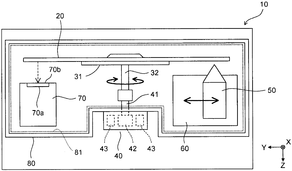
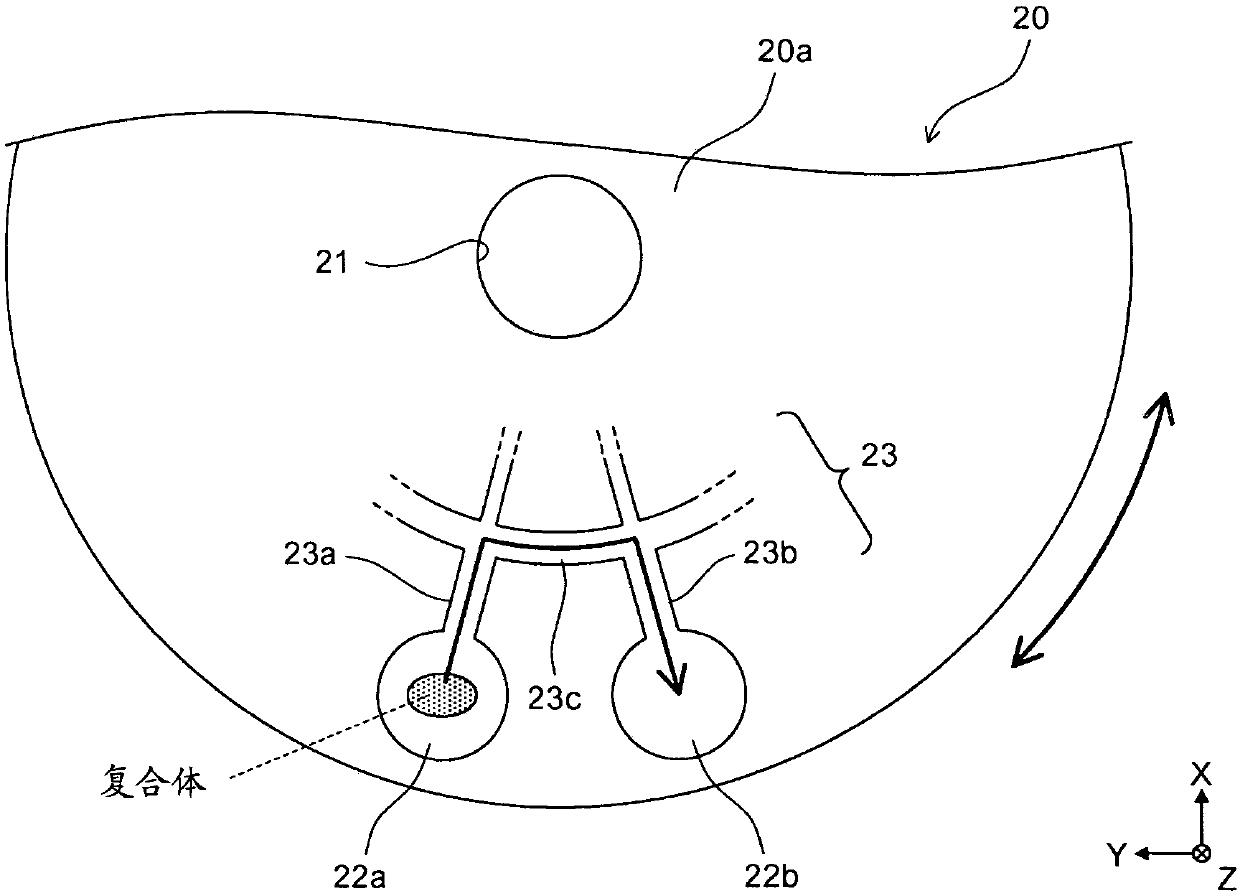
[0144] The outline of the chemiluminescence measurement device and the cartridge according to Embodiment 1 will be described with reference to FIGS. 1( a ) and ( b ).
[0145] As shown in FIG. 1( a ), the chemiluminescence assay device 10 is an immunoassay device for measuring a test substance in a sample by using an antigen-antibody reaction. The chemiluminescence measurement device 10 measures a substance to be measured contained in a sample by chemiluminescence measurement using the cartridge 20 .
[0146]Chemiluminescence refers to light emitted using energy generated by a chemical reaction. For example, it is light emitted when a molecule is excited by a chemical reaction to become an excited state and returns to a ground state from the excited state. Chemiluminescence can be generated, for example, by a reaction between an enzyme and a substrate, or by applying an electrochemical stimulus to a labeling substance, or based on the LOCI method (Luminescent Oxygen Channeling...
Embodiment approach 2
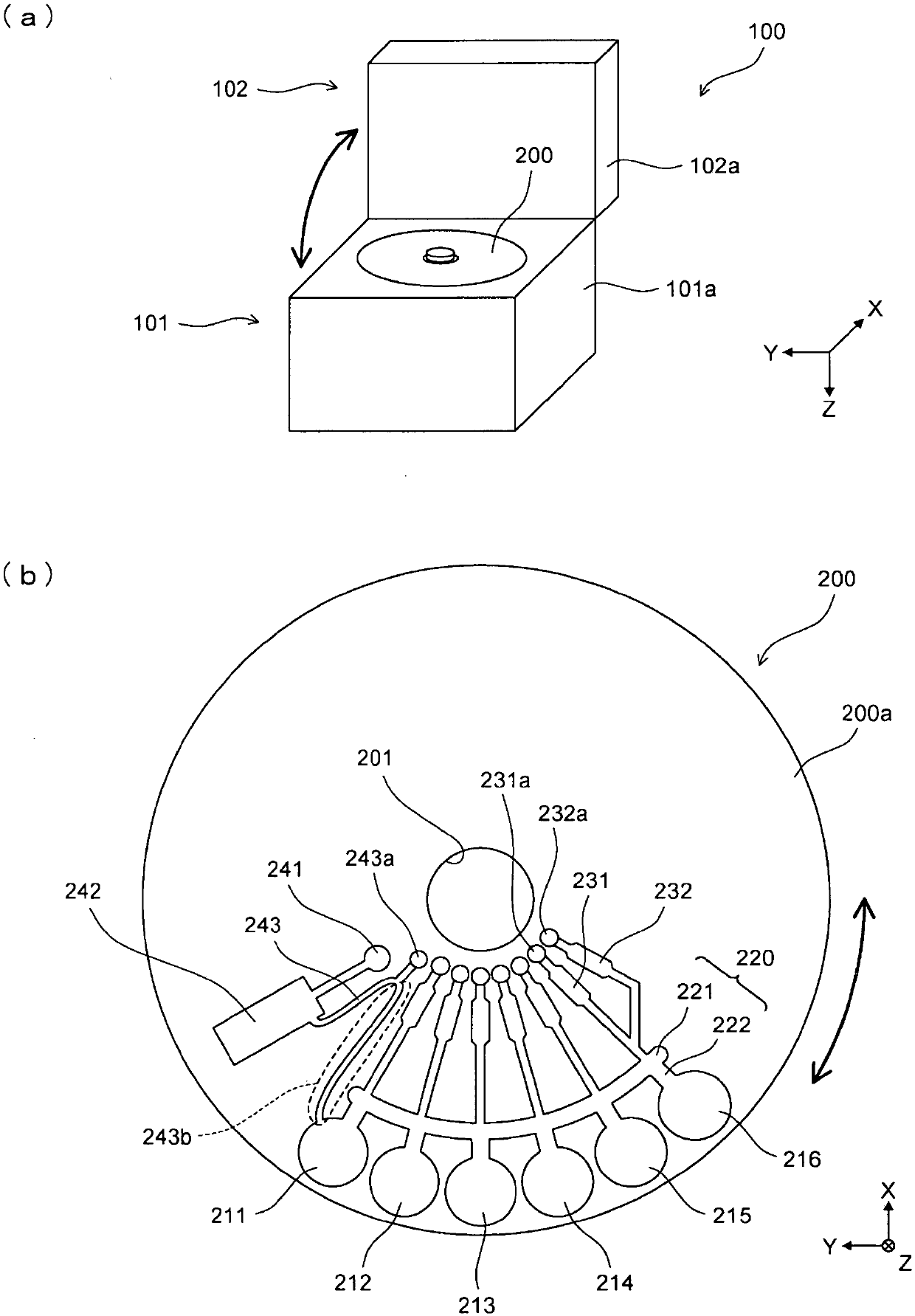
[0313] In Embodiment 1, as referred to figure 2 (a) As already described, the cartridge 200 is set in the analysis device 100 by opening the lid 102 . In Embodiment 2, such as Figure 21As shown in (a), the cartridge 200 is set inside the analysis device 400 with the tray 402 moved to the outside through the hole 401 a provided on the front surface of the housing 401 of the analysis device 400 .
[0314] A light shielding member 403 is provided at the front end of the tray 402 . The outer shape of the light shielding member 403 is slightly larger than that of the hole 401a. A light-shielding elastic member 404 is provided around the exit of the hole 401a. When the tray 402 moves inside, the hole 401 a is blocked by the light shielding member 403 and the elastic member 404 . The rest of the configuration of the analysis device 400 is substantially the same as the specific configuration example of the analysis device 100 according to the first embodiment.
[0315] Also in ...
Embodiment approach 3
[0317] In Embodiment 3, such as Figure 21 As shown in (b), a support member 510 is arranged instead of the support member 177 , and a case body 520 is used instead of the case body 200 . The other configurations are the same as the specific configuration example of the first embodiment.
[0318] The supporting member 510 has a hole 511 and three setting portions 512 . A hole 511 is provided at the center of the support member 510 . The support member 510 is provided on the rotation shaft 311 via a predetermined member. Thereby, the support member 510 can rotate around the rotation shaft 311 . Three setting parts 512 are provided in the circumferential direction. The installation part 512 has a surface 512a and a hole 512b. The surface 512 a is one step lower than the upper surface of the supporting member 510 . The hole 512b is formed in the center of the surface 512a, and penetrates the support member 510 in the vertical direction. The case body 520 is rectangular in ...
PUM
 Abstract
Description
Claims
Application Information
 - R&D
- Intellectual Property
- Life Sciences
- Materials
- Tech Scout
- Unparalleled Data Quality
- Higher Quality Content
- 60% Fewer Hallucinations
Browse by: Latest US Patents, China's latest patents, Technical Efficacy Thesaurus, Application Domain, Technology Topic, Popular Technical Reports.
© 2025 PatSnap. All rights reserved.Legal|Privacy policy|Modern Slavery Act Transparency Statement|Sitemap|About US| Contact US: help@patsnap.com