Construction method of screw drilling and squeezing cast-in-place pile and combined screw drill

A construction method and cast-in-situ pile technology, which is applied in the direction of drill bits, sheet pile walls, drilling equipment, etc., can solve the problem that the drilling capacity of bored cast-in-place piles cannot be driven in, which affects the quality of piles and the cost of pile foundations, and the difficulty of punching cast-in-situ piles. Hole collapse and other problems, to achieve the effect of strong constructability, high construction efficiency, and small settlement

Pending Publication Date: 2018-01-12
浙江坤德创新岩土工程有限公司
View PDF4 Cites 2 Cited by
  • Summary
  • Abstract
  • Description
  • Claims
  • Application Information

AI Technical Summary

Problems solved by technology

[0002] In the pile foundation construction of hard ground, pebble gravel and other strata, the traditional construction technology has many shortcomings, such as the limited drilling capacity of bored piles and cannot be driven in; punched cast-in-place piles are prone to collapse, and the verticality is difficult to control. The hole-forming effect is not ideal and the f...

Method used


Image

  • Construction method of screw drilling and squeezing cast-in-place pile and combined screw drill
  • Construction method of screw drilling and squeezing cast-in-place pile and combined screw drill
  • Construction method of screw drilling and squeezing cast-in-place pile and combined screw drill

Examples


Embodiment Construction

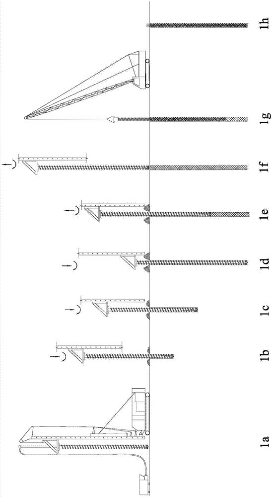
[0035] Such as figure 1 middle figure 1 Shown in a ~ 1h, the construction method of the screw-drilled cast-in-place pile of the present invention comprises the following construction steps:

[0036] 1) The pile drill rig equipped with the combined screw drill bit is put in place according to a known method, the concrete pump is prepared, and the pile material to be poured is prepared. Conventional piles are concrete or cement fly ash gravel piles and the like.

[0037] 2) After the pile drilling rig with the combined screw drill bit is in place, start the pile drilling rig to apply clockwise torque and downward axial pressure, and use the combined screw drill bit to drill and extrude the hole. During the process, the soil loosened by rotary drilling is transported to the surface through the rotating motion of the helical blade on the drill bit system, and part is gradually squeezed into the side wall of the pile hole. The pile hole drilling and squeezing process in the first...


PUM


Abstract

The invention discloses a construction method of a screw drilling and squeezing cast-in-place pile. The construction method comprises the following steps: a combined screw drill is rotated clockwise for drilling and squeezing hole forming in advance; after a designed depth is reached, the combined screw drill is enabled to move upwards and rotated clockwise again to squeeze and expand a pile hole;the combined screw drill is screwed upwards, and at the same time, a concrete pump is started to fill the pile hole with a piling material to a preset height; and then a reinforcement cage is implanted. The combined screw drill comprises a spiral drill pipe at the upper part and a screw-type drilling and tunneling head at the lower part, wherein the upper end of the spiral drill pipe is connectedwith a power head; the lower end of the spiral drill pipe is connected with the screw-type drilling and tunneling head at the lower part; the screw-type drilling and tunneling head consists of a drill reducing segment and a drill cutting pick segment; the diameter of the drill reducing segment is gradually reduced from the upper end to the lower end to a certain set diameter; and meanwhile, alloycutting picks are distributed at the end part of the drill cutting pick segment. The screw drilling and squeezing cast-in-place pile constructed by the combined screw drill has the characteristics ofstrong constructability on a hard stratum, high bearing capacity, small sedimentation, good piling quality, lower cost, less energy consumption and the like.

Description

technical field [0001] The invention relates to the field of geotechnical engineering, in particular to a construction method for screw-drilled cast-in-situ piles and a combined screw drill bit. Background technique [0002] In the pile foundation construction of hard ground, pebble gravel and other strata, the traditional construction technology has many shortcomings, such as the limited drilling capacity of bored piles and cannot be driven in; punched cast-in-place piles are easy to collapse holes, and the verticality is difficult to control. The hole-forming effect is very unsatisfactory and the filling coefficient is too large, which affects the quality of the pile and the cost of the pile foundation; screw piles and spiral squeezed soil piles are also difficult to advance due to excessive drilling resistance, insufficient torque of the power head, and deformation of the spiral blades. Affect the life of the pile driver and the construction period of the project. Conte...

Claims


Application Information

Patent Timeline
IPC IPC(8): E02D5/36E21B10/44E21B10/54
Inventor 吕美东陈天雄
Owner 浙江坤德创新岩土工程有限公司
Why Eureka
Try Eureka