
Multi-chamber heat accumulating type oxidation furnace

An oxidation furnace and regenerative technology, which is applied in the field of multi-chamber regenerative oxidation furnace, can solve the problems of RTO not being able to work continuously, difficulty in meeting national standards, and high emission concentration, achieving remarkable energy-saving effects, improving service life, and saving energy Effect

Pending Publication Date: 2018-01-12
NANJING CEEP TECH
View PDF0 Cites 3 Cited by
  • Summary
  • Abstract
  • Description
  • Claims
  • Application Information

AI Technical Summary

Problems solved by technology

Because the exhaust temperature is higher than the intake temperature, resulting in volume expansion and VOCs incineration to generate gas, the exhaust volume flow rate is about 1.4 times that of the intake volume flow rate; in addition, the structure of the high and low temperature ends of the regenerator is different, resulting in the difference between the intake and exhaust Under the same cross-sectional area of ​​the flow channel, the exhaust pressure loss is about twice that of the intake pressure loss; in addition, the combustion air is not preheated, and the above defects may cause the RTO to not work continuously, thus wasting fuel
[0005] In addition, because the leakage rate of the rotary reversing valve of the oxidation furnace is difficult to be stably controlled below 1% or even lower for a long time, the emission concentration is still high when dealing with exhaust gas with high VOC concentration, and it is difficult to meet the national standard

Method used


Image

  • Multi-chamber heat accumulating type oxidation furnace
  • Multi-chamber heat accumulating type oxidation furnace
  • Multi-chamber heat accumulating type oxidation furnace

Examples


Embodiment Construction

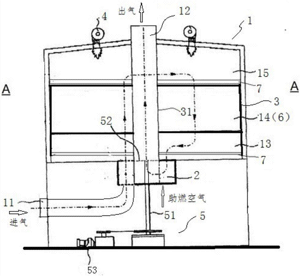
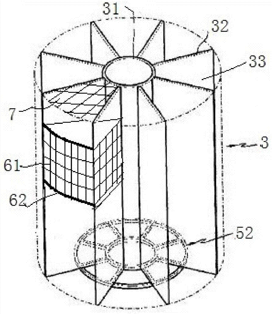
[0043] combine Figure 1 to Figure 4As shown, the embodiment discloses a multi-chamber regenerative oxidation furnace, which includes an oxidation furnace body 1, a gas distribution device 2, a segmentation device 3, a combustion-supporting device 4, a rotating device 5, a heat storage device 6 and a gas uniform distribution device 7.

[0044] Oxidation furnace body 1 is cylindrical structure, has an air intake pipe 11 and an exhaust pipe 12, and air intake pipe 11 is connected with the inlet end of oxidation furnace body 1, and exhaust pipe 12 is arranged in the middle of oxidation furnace body 1 top position and is connected to the gas outlet of the oxidation furnace body 1.

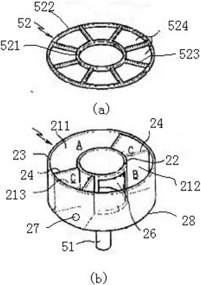
[0045] The gas distribution device 2 is fixed in the middle of the bottom surface of the oxidation furnace body 1. It is an inner and outer double-layer cylindrical structure with an open top surface, that is, the distribution inner cylinder 22 and the distribution outer cylinder 23. There are four pi...


PUM


Abstract

The invention discloses a multi-chamber heat accumulating type oxidation furnace. The multi-chamber heat accumulating type oxidation furnace comprises an oxidation furnace body, an air inlet pipeline,an exhausting pipeline, a gas distribution device, a division device, an combustion-supporting device and a rotary device, wherein the division device is located inside the oxidation furnace body andis used for dividing the oxidation furnace body into a reaction chamber and a gas distribution chamber; the gas distribution chamber is divided into a plurality of mutually independent fan-shaped division chambers by a plurality of division plates; the gas distribution device is of an internal and external double-layer barrel structure and comprises an air inlet area A, an air outlet area B and at least two combustion-supporting air areas C; the air inlet area A and the air outlet area B are spaced by the combustion-supporting air areas C; the rotary device drives the division device to rotate together; and the volume of the air outlet area B is larger than that of the air inlet area A. The multi-chamber heat accumulating type oxidation furnace has the beneficial effects that the pressureloss of the whole device can be reduced, the continuous operation of the device is ensured, the working efficiency of the multi-chamber heat accumulating type oxidation furnace is improved, and energy sources are saved.

Description

technical field [0001] The invention belongs to the technical field of exhaust gas incinerators, and in particular relates to a multi-chamber regenerative oxidation furnace. Background technique [0002] The multi-chamber regenerative thermal oxidizer (Regenerative Thermal Oxidizer, RTO for short) is a kind of energy-saving and environmental protection equipment used to treat medium and low concentration volatile organic waste gas. The basic principle of RTO is to oxidize organic waste gas to generate CO2 and H2O at high temperature (>760°C), so as to remove them. RTO uses ceramic heat storage, which can maximize the recovery and reuse of heat energy, the heat recovery rate is greater than 95%, and it does not use or use very little fuel when dealing with VOCs. This type of device has the following characteristics: 1) Low operating cost and ultra-low fuel cost. When the organic waste gas concentration is above a certain range, the RTO device does not need to add auxilia...

Claims


Application Information

Patent Timeline
IPC IPC(8): F23G7/06
Inventor 孙颖肖宏鹰丁金明陈勇刘训稳
Owner NANJING CEEP TECH
Learn More