Magnetizing cutter, machining method and using method thereof, cutting fluid and preparation method
A processing method and cutting fluid technology, applied in metal processing equipment, turning equipment, cutting tools for lathes, etc., can solve problems such as easy sticking of knives, insufficient lubrication of the knife-swarf contact interface, and excessive loss of solid lubricants , to achieve the effect of enhancing the quality of the tool, improving the lubrication effect, and improving the quality of the tool
- Summary
- Abstract
- Description
- Claims
- Application Information
AI Technical Summary
Problems solved by technology
Method used
Image

Examples
Embodiment 1
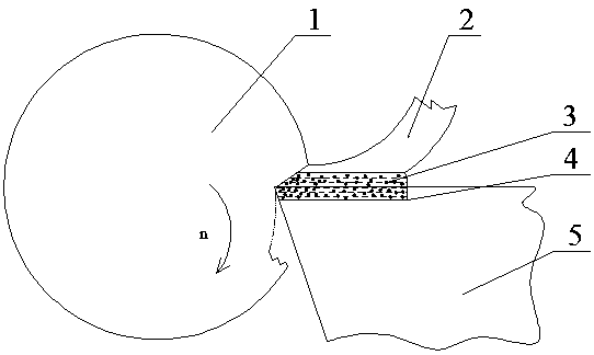
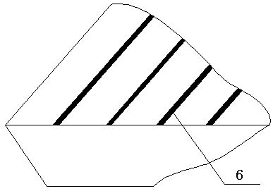
[0025] In this example, if figure 1 and 2 , the cutting tool 5 is a hard alloy cylindrical turning tool, the cutting material 1 is titanium alloy; the magnetic fluid cutting fluid 3 is Fe 3 o 4 Oil-based magnetic fluid; surface texture appearance 4 is micro-grooves; fiber laser is selected to output Gaussian distribution infrared laser.
[0026] The implementation of the technical features of the present invention includes the following steps.
[0027] In step A, the tool 5 is magnetized using pulse magnetization technology, and the processing parameters are: processing time 60s, frequency 2Hz, and pulse magnetic field strength 800Gs.
[0028] Step B, surface pretreatment of the cutter 5, polishing the surface to be processed on the cutter 5 so that the surface roughness Ra is less than 0.4 μm.
[0029] Step C, determine the area and density of the surface texture. In this embodiment, the texture area is the contact area between the tool and the chip on the rake face and t...
Embodiment 2
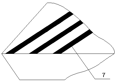
[0035] In this example, if figure 1 and 3 , the tool 5 is a high-speed steel cylindrical turning tool, the cutting material 1 is aluminum alloy; the magnetic fluid cutting fluid 3 is an iron-cobalt alloy powder oil-based magnetic fluid; the surface of the tool 5 has a guide groove 4.
[0036] The implementation of the technical features of the present invention includes the following steps.
[0037] In step A, the tool 5 is magnetized, using AC magnetization technology, and the processing parameters are: processing time 45s, frequency 2Hz.
[0038] Step B, surface pretreatment of the cutter 5, polishing the surface to be processed on the cutter 5 so that the surface roughness Ra is less than 0.4 μm.
[0039] Step C, determine the area and density of the diversion groove 4. In this embodiment, the region of the diversion groove 4 is the contact area between the tool and the chip on the rake face and the contact area between the tool rake face and the workpiece; the area occup...
PUM
 Abstract
Description
Claims
Application Information
 - Generate Ideas
- Intellectual Property
- Life Sciences
- Materials
- Tech Scout
- Unparalleled Data Quality
- Higher Quality Content
- 60% Fewer Hallucinations
Browse by: Latest US Patents, China's latest patents, Technical Efficacy Thesaurus, Application Domain, Technology Topic, Popular Technical Reports.
© 2025 PatSnap. All rights reserved.Legal|Privacy policy|Modern Slavery Act Transparency Statement|Sitemap|About US| Contact US: help@patsnap.com